-
Book Overview & Buying
-
Table Of Contents

-
Feedback & Rating

Unreal Engine 5 Character Creation, Animation, and Cinematics
By :
Unreal Engine 5 Character Creation, Animation, and Cinematics
By:
Overview of this book
Unreal Engine 5 (UE5) offers beginners and seasoned professionals the ability to create detailed movie scenes with realistic human characters using MetaHuman and combine it with custom props and environments. It also comes with built-in industry standard animation tools to develop such scenes in a fraction of the time compared to old methods. This book takes you through the entire 3D movie production pipeline using free (open - source) software.
By following the step-by-step, beginner-friendly tutorials in this book, you'll learn how to create your own custom 3D assets in Blender and texture these 3D assets in Quixel Mixer. Next, you'll take these completed 3D assets into Unreal Engine 5 and use them to build a virtual 3D movie set for your 3D movie. You'll also populate your 3D movie set by using Quixel MegaScans assets and create and customize your own photorealistic human character using MetaHuman Creator and UE5. As you advance, you'll discover how to rig, skin, and animate these 3D assets and characters using Blender and UE5's new Control Rig. Finally, you'll explore the process of setting up your movie cameras and animation sequences and rendering your 3D movie using UE5's Sequencer.
By the end of this Unreal Engine book, you'll have learned how to combine different elements in UE5 to make your own movies and cinematics.
Table of Contents (27 chapters)
Preface

Part 1 Creating 3D Assets
 Free Chapter
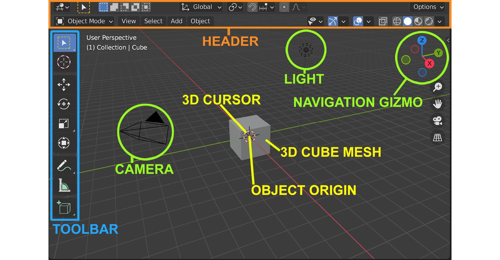
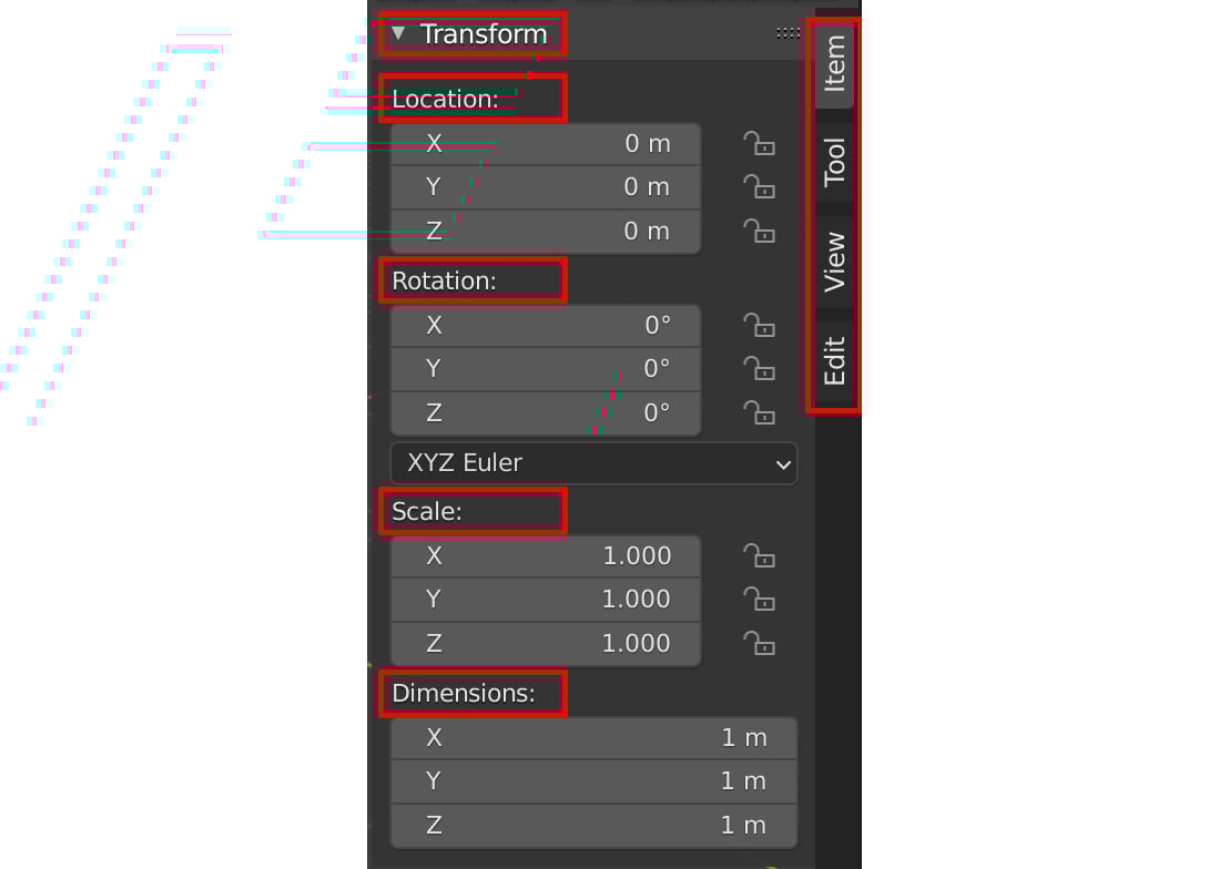
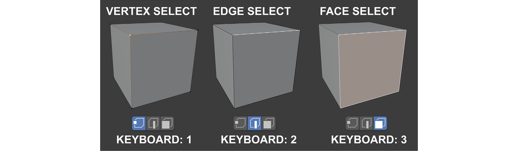
Chapter 1: An Introduction to Blender's 3D Modeling and Sculpting Tools
Chapter 2: Modeling a Robot Drone Character
Chapter 3: Let's Sculpt an Alien Plant!
Chapter 4: UV Maps and Texture Baking
Chapter 5: Texturing Your Models inside Quixel Mixer
Part 2 Building Your Virtual Movie Set in Unreal Engine 5
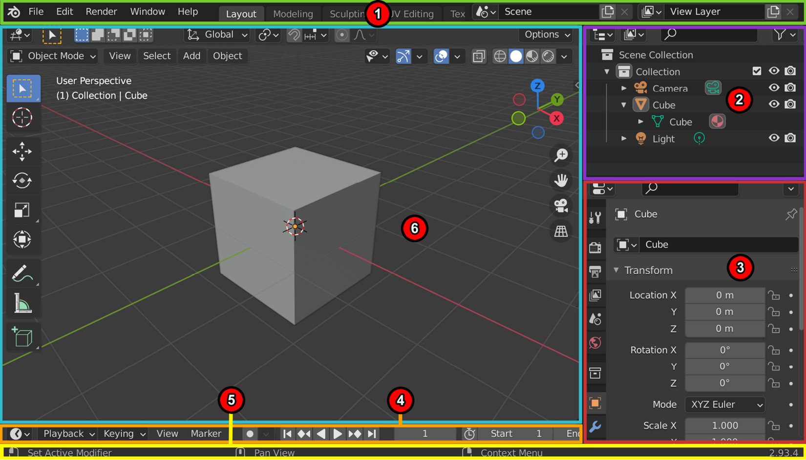
Chapter 6: Exploring Unreal Engine 5
Chapter 7: Setting Up Materials in UE 5
Chapter 8: Using MetaHuman to Create a Photorealistic Human for UE5
Chapter 9: Building a Virtual 3D Movie Set in UE5
Chapter 10: Adding Lighting and Atmospheric Visual Effects in UE5
Part 3 Character Rigging for Animation in UE5 with Control Rig
Chapter 11: Alien Plant Joint Setup in Blender
Chapter 12: Alien Plant Skinning in Blender
Chapter 13: Robot Joint Setup and Skinning in Blender
Chapter 14: Making a Custom Rig for Our Alien Plant with Control Rig
Chapter 15: Creating a Control Rig with Basic IK Controls for the Robot in UE5
Part 4 Animation in UE5 Using Control Rig and Sequencer
Chapter 16: Creating a Simple Swaying Animation Cycle in UE5 Sequencer
Chapter 17: Creating Three Simple Animations for the Robot in UE5 Sequencer
Chapter 18: Importing Motion Capture onto the MetaHuman Control Rig
Chapter 19: Motion Capture Editing and Cleanup Using Control Rig and Sequencer
Chapter 20: Using Sequencer to Construct Your Final Scene
Index
Customer Reviews