-
Book Overview & Buying

-
Table Of Contents

-
Feedback & Rating

Taking Blender to the Next Level
By :
Taking Blender to the Next Level
By:
Overview of this book
If you're ready to start exploring the more advanced workflows and processes in Blender to create intricate 3D models, then Taking Blender to the Next Level is for you.
This book focuses on a few different VFX-related workflows such as geometry nodes, organic modeling, 3D camera tracking, photogrammetry, sculpting, compositing, and physics simulations. You’ll learn how to use geometry nodes to create dynamic motion graphic scenes as well as perform 3D scanning of real-world objects using photogrammetry. You’ll also find out how to model, rig, and animate your own 3D characters from scratch. Next, you’ll progress to using simulations to break objects apart and then use cloth and hair simulations to add realism to your 3D creations. Finally, you’ll go over the final render settings and export your 3D animation masterpiece as a video.
By the end of this Blender book, you’ll be able to model your own 3D characters, objects, and landscapes; rig, animate, and texture your characters; 3D track live-action footage; and composite your 3D characters into live-action scenes.
Table of Contents (19 chapters)
Preface
In Progress
| 0 / 9 sections completed |
0%

Part 1: Modeling, Materials, and Animation Workflows
In Progress
| 0 / 1 sections completed |
0%
 Free Chapter
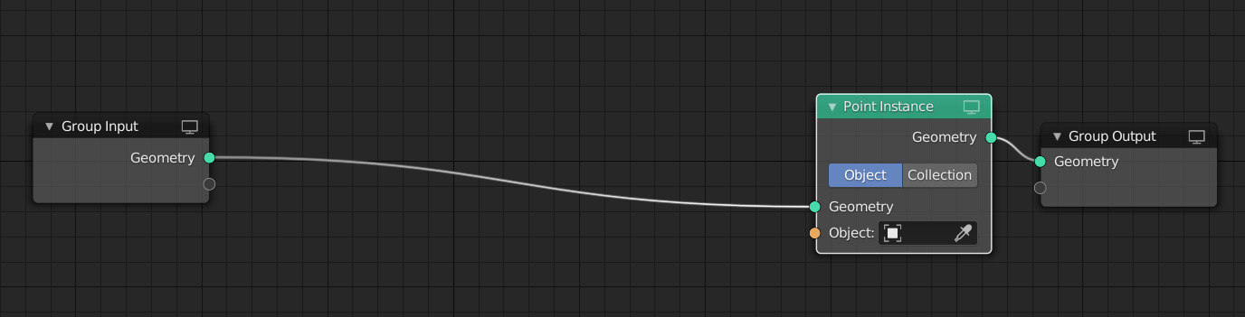
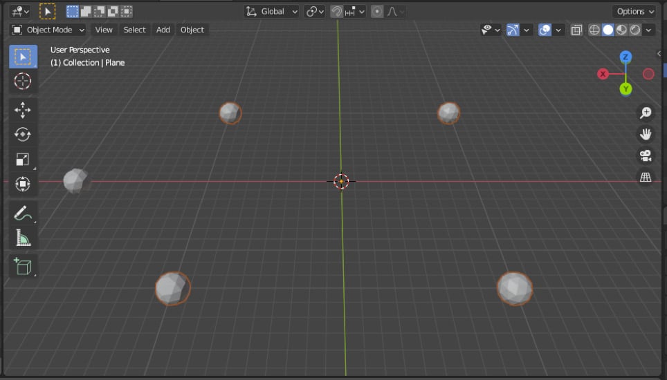
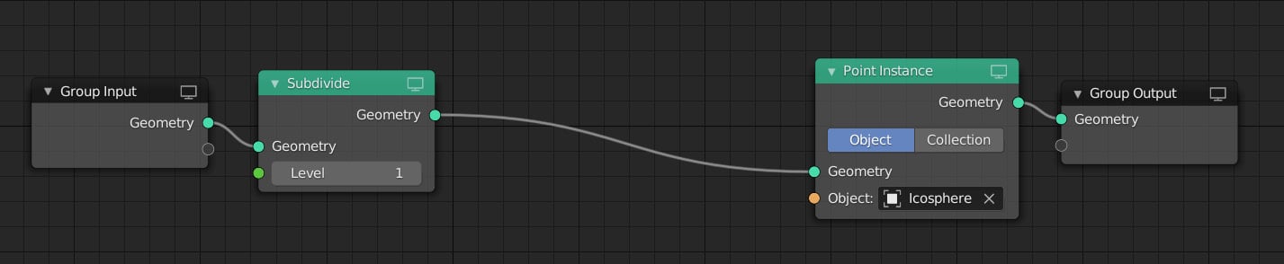
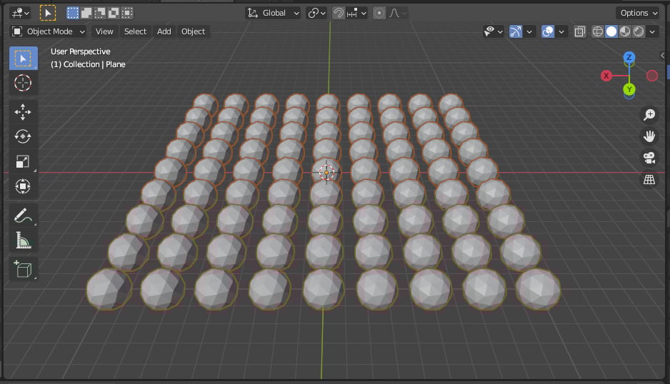
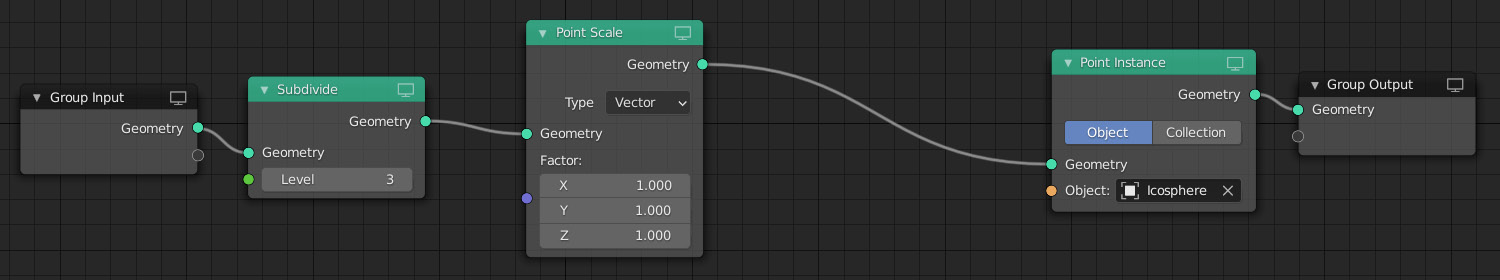
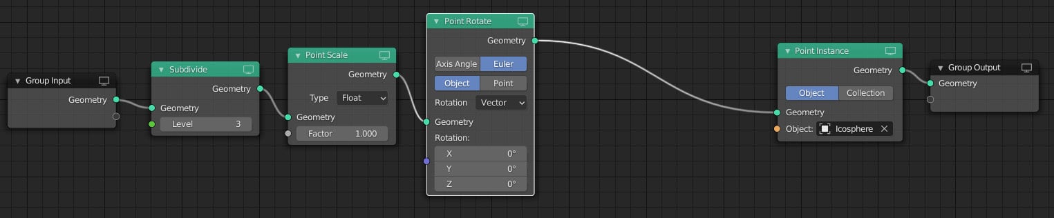
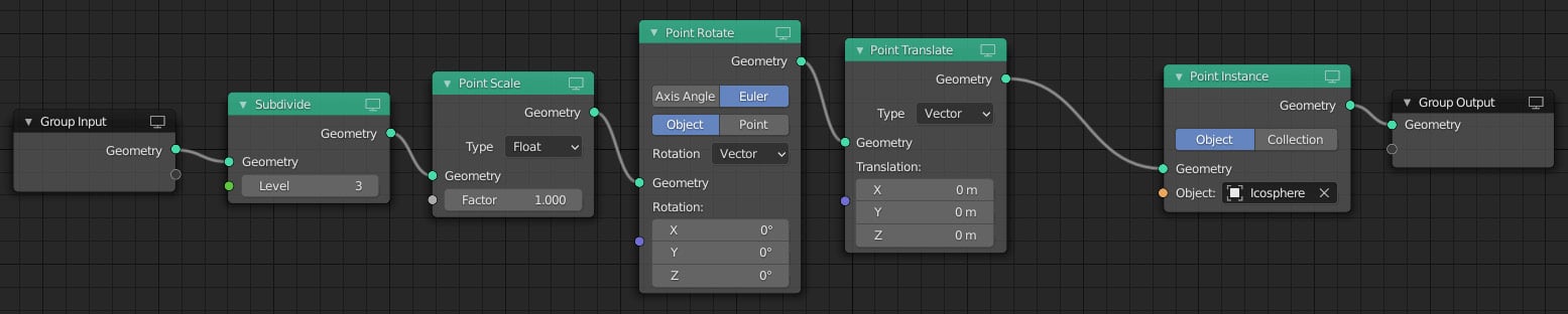
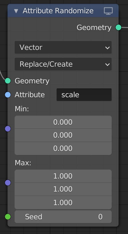
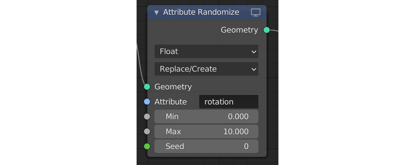
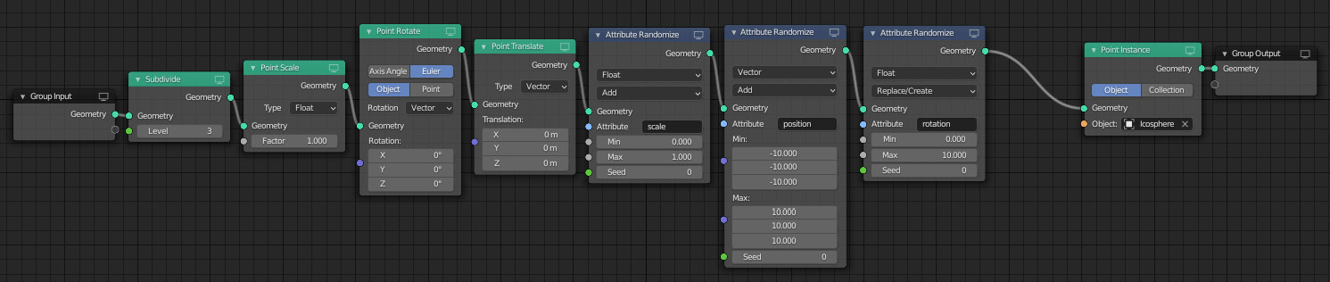
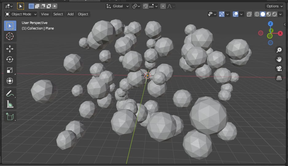
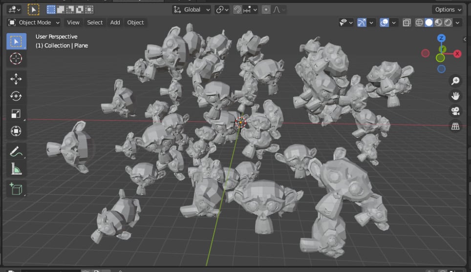
Chapter 1: Using Geometry Nodes to Create Dynamic Scenes
In Progress
| 0 / 6 sections completed |
0%
Chapter 2: Creating a Motion Graphics Scene Using Geometry Nodes
In Progress
| 0 / 7 sections completed |
0%
Chapter 3: Organic Modeling P1: Creating a Mushroom
In Progress
| 0 / 9 sections completed |
0%
Chapter 4: Organic Modeling P2: Creating the Landscape around the Mushroom
In Progress
| 0 / 4 sections completed |
0%
Chapter 5: PBR Materials: Texturing our Mushroom Scene
In Progress
| 0 / 6 sections completed |
0%
Chapter 6: 3D Scanning and Photogrammetry: Creating Your Own 3D Scans
In Progress
| 0 / 7 sections completed |
0%
Chapter 7: Modeling an Alien Cartoon Character
In Progress
| 0 / 5 sections completed |
0%
Chapter 8: Rigging and Animating Your 3D Cartoon Character
In Progress
| 0 / 7 sections completed |
0%
Part 2: Let's Do Some Physics
In Progress
| 0 / 1 sections completed |
0%
Chapter 9: Rigid Body Simulation: Destroying a Statue Using Physics
In Progress
| 0 / 10 sections completed |
0%
Chapter 10: Dynamic Cloth Simulations
In Progress
| 0 / 9 sections completed |
0%
Chapter 11: Creating Dynamic Hair Using Particles
In Progress
| 0 / 8 sections completed |
0%
Part 3: Match Moving and Compositing
In Progress
| 0 / 1 sections completed |
0%
Chapter 12: Matching Blender's Camera Movement to Live Action Footage
In Progress
| 0 / 7 sections completed |
0%
Chapter 13: Compositing the Alien Cartoon Character onto the Live Action Footage
In Progress
| 0 / 6 sections completed |
0%
Chapter 14: The Final Render
In Progress
| 0 / 6 sections completed |
0%
Other Books You May Enjoy
In Progress
| 0 / 3 sections completed |
0%
Customer Reviews