In this recipe, you will create an assembly of part of a crane hook from an existing .dwg file using the top-down methodology of layout design. Any changes made to the sketch will be reflected in the 3D model. The steps to create this are, firstly, to create the layout itself in 2D, import the 2D layout into Inventor, define the sketch blocks, and, finally, make the parts and components using the feature commands in Inventor.
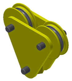
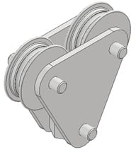
You can see the final assembly of the completed crane hook in Figure 2.25:
Figure 2.25: The final assembly of the crane hook you will create in this recipe
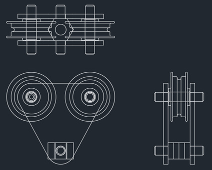
The original 2D AutoCAD drawing from which this was created is shown in Figure 2.26:
Figure 2.26: The original 2D layout shown in AutoCAD that we will create the 3D assembly from
Getting ready
Navigate to the Chapter 2 folder in Inventor Cookbook 2023 and open the Crane Hook folder. Then, select the 459-25.iam assembly file to look at the completed design in 3D.
The 2D drawing we will create this from can be found in the Crane Hook folder, filename: Crane_Hook.dwg. Figure 2.26 shows the original 2D layout we will use.
To begin, you will need to open a new Metric Standard (mm).ipt file. Have this open and ready before starting the recipe. The original drawing is already drawn to scale 1:1 and does not need dimensional changes when creating the 3D parts; this is simply for reference. The reason for using this methodology is that quite often, at the concept stage, designers create an overall 2D layout in a 2D CAD package, such as AutoCAD, and then require a 3D design for detailed design and manufacturing drawings. This is not the only way to use .dwg files within Inventor.
In this recipe, the original drawing is supplied as a 2D AutoCAD Crane_Hook.dwg file. You do not need AutoCAD to complete this recipe; only Inventor will be used.
How to do it…
To start, we will need to open Inventor and import the original 2D CAD data:
- Create a new
Metric Standard (mm).ipt file.
- Then, create a new sketch on the XY plane. This will become the plane to which we will import the existing
.dwg 2D drawing of the layout, which will form the basis of the assembly. Because the parts are already drawn to scale and in place, minimal constraining and dimensional input are required, as this has already been completed in the AutoCAD Crane_Hook.dwg drawing file.
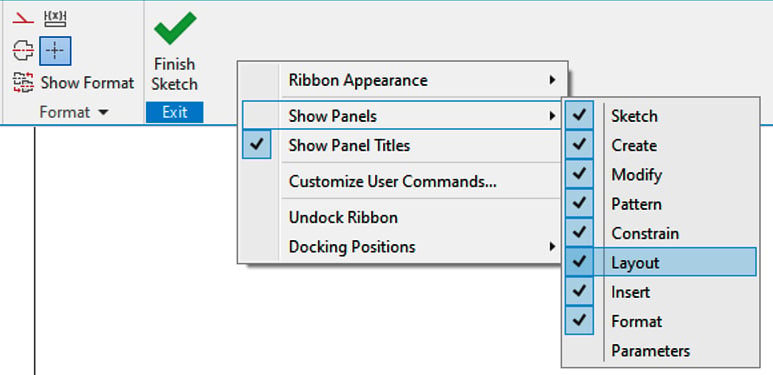
- With the new sketch active, navigate to the ribbon. In the blank area after Finish Sketch (shown in Figure 2.27), right-click so that a menu pops up. Then, select Show Panels, then Layout, so that a tick is applied. This loads the Layout commands to the ribbon, which will be required for the next steps in this recipe.
Figure 2.27: Layout panel added to the ribbon
- Next, navigate to the ribbon. In the Insert tab, select the ACAD button.
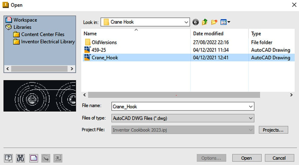
- You will now import the original 2D AutoCAD drawing into Inventor so that you can use the existing geometry and create the model. Select ACAD, then browse to the
Crane Hook folder and select the Crane_Hook.dwg file. Then, click Open.
Figure 2.28: Crane_Hook.dwg location shown
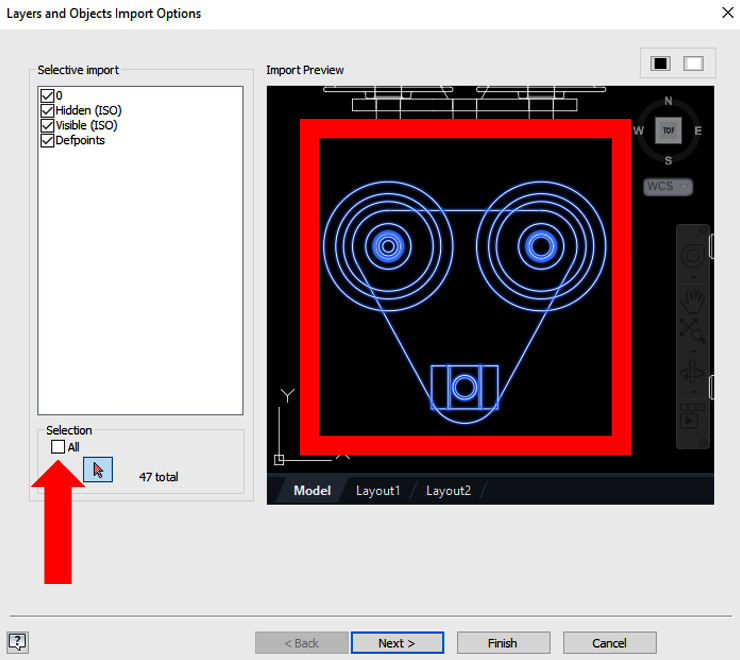
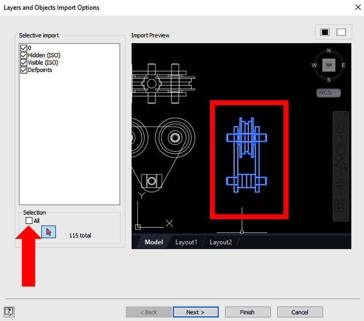
- The Layers and Objects Import Options tab has now opened, which allows you to include or exclude certain AutoCAD geometry from the
.dwg file for import. Untick the All box and click the selection arrow. Then, select the geometry highlighted in Figure 2.28. Now, you can click Finish. This will import only this highlighted geometry from the model. Then, select Next, followed by Finish.
Figure 2.29: Selected geometry we require
Now, the selected geometry will appear in the sketch.
To move the imported geometry to the correct position, we first need to create this as a sketch block. Select Create Block from the recently added Layout tools in the ribbon.
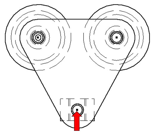
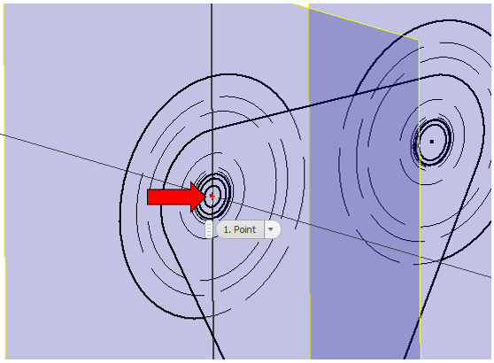
- Select all the geometry that was imported and then select the insertion point (Figure 2.30) as the center of the bottom circle. Click OK to complete the creation of the sketch block. You have now created a sketch block that can be constrained.
Figure 2.30: Insertion point for the sketch block
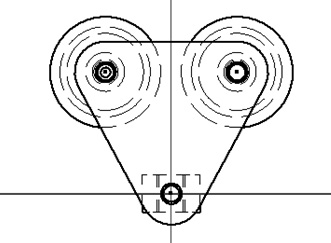
- Next, use Coincident Constrain to constrain the center of the insertion point of the sketch block to the origin of the file, then select Finish Sketch.
Figure 2.31 shows the newly created sketch block constrained to the origin:
Figure 2.31: Sketch block of imported geometry constrained to origin
- Turn on the visibility of the YZ plane by right-clicking the YZ plane in the Model Browser and selecting Visibility; this turns the visibility of the plane on.
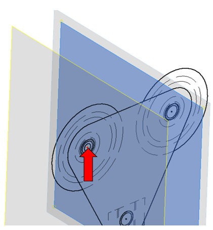
- Select Plane and then select the YZ plane as the first reference. For the second reference, select the center of the top-left circle of the sketch block, as shown in Figure 2.32:
Figure 2.32: Plane creation using the existing YZ plane and reference point on the sketch block
- The newly created Workplane 1 will act as the reference plane for the next sketch and the next piece of imported geometry. Select Start 2D Sketch on Workplane 1.
- Select the ACAD import button and import the
Crane_Hook.dwg file. This time, select only the geometry shown in Figure 2.33 and click Next followed by Finish to import the geometry into the sketch:
Figure 2.33: The geometry that is required for the second import option
- Create a sketch block of the newly imported geometry with the same process previously shown in steps 7 and 8.
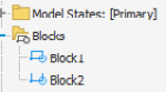
- Upon completion of these two sketch blocks, the Blocks folder in the Model Browser should show two sketch blocks: Block1 and Block2.
Figure 2.34: Block1 and Block2 in the Model Browser
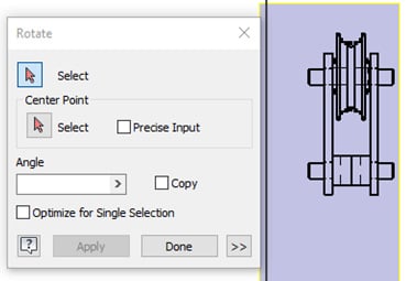
- Edit Sketch2 from the Model Browser, that contains Block2, select the Sketch tab, and select Rotate from the Modify tools to rotate the sketch block to the orientation shown in Figure 2.35. Ensure your sketch matches that of Figure 2.35:
Figure 2.35: Rotate used to rotate the sketch block in sketch mode to the orientation shown
- Save the file as
Crane_Hook_Layout.ipt.
- Now that the sketch block has been created and is in the correct orientation, it needs to be constrained in context with the first sketch block that was created. Edit the sketch that contains Block2 that you rotated. Select the Project Geometry command and project the point shown in Figure 2.36:
Figure 2.36: Point to project for the second imported sketch
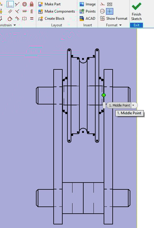
- In the same sketch, select the coincident constraint. Pick the mid-point shown in Figure 2.37 as the first reference:
Figure 2.37: The first reference to select
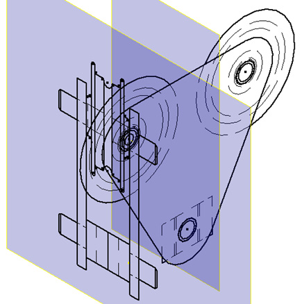
- For the second reference, select the projected point created in step 17. The sketch block should then be constrained in the position shown in Figure 2.38:
Figure 2.38: Two sketch blocks constrained and in position
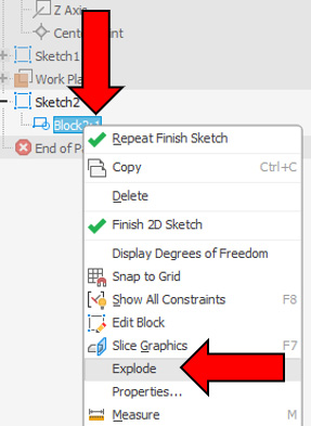
Now that the sketch blocks are in position, we will explode them. This is to separate the individual sketch elements so that individual components can be made from them. The reason they were converted to sketch blocks was to enable us to constrain them first to the origin and then to each other in the correct location. Doing this allows us to utilize all aspects of the 2D views of the crane hook provided.
- In Model Bowser, expand the Sketch2 node and right-click on Block2:1, then select Explode. Then, select Finish Sketch from the ribbon.
Figure 2.39: Sketch2 expanded and Block2:1 exploded
- In the Model Browser, click on the Block1 name and rename it to
CH_Plate.
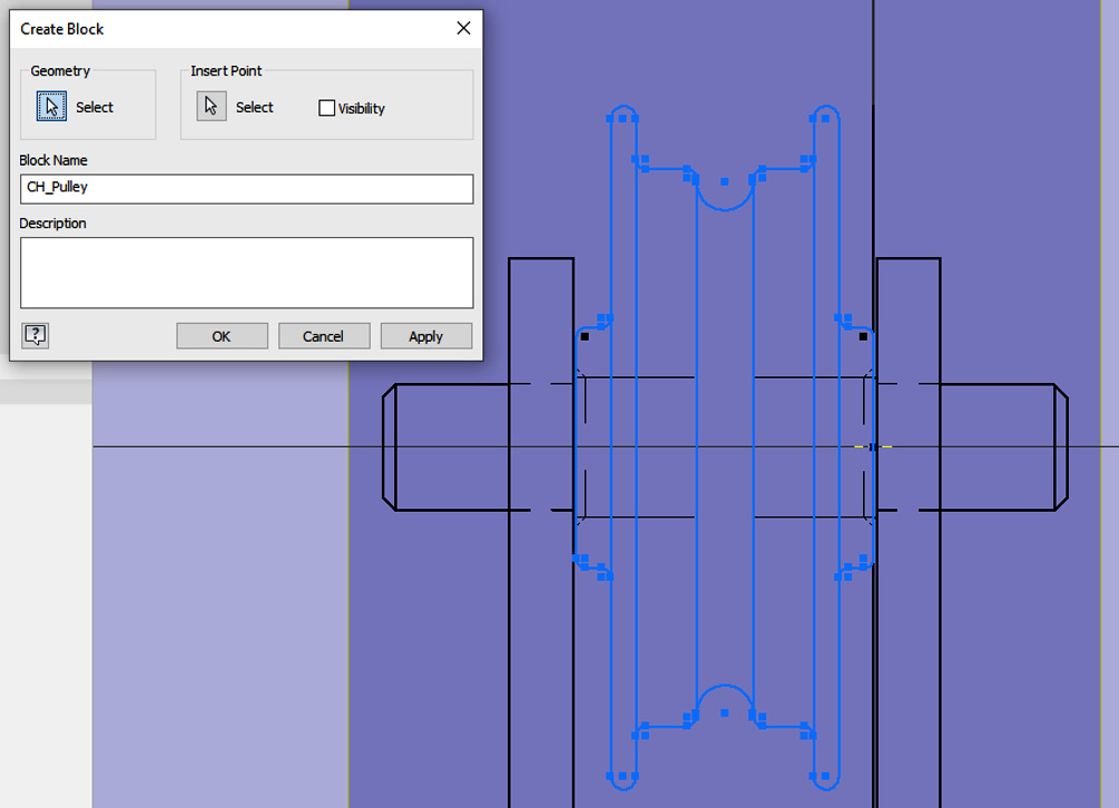
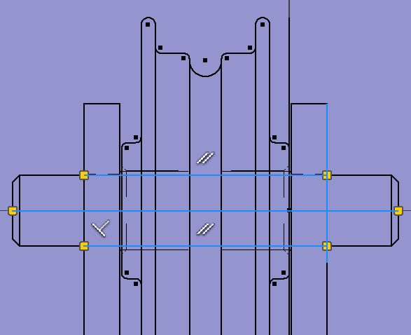
- Select Edit Sketch for Sketch2. Select Create Block, then select the geometry shown in Figure 2.40. Set the name of the block to
CH_Pulley. Click OK.
Figure 2.40: CH_Pulley block created
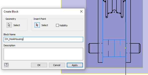
- Create another new sketch block; in this instance, select the geometry shown in Figure 2.41 and set the name as
CH_HookHousing:
Figure 2.41: CH_HookHousing sketch block created
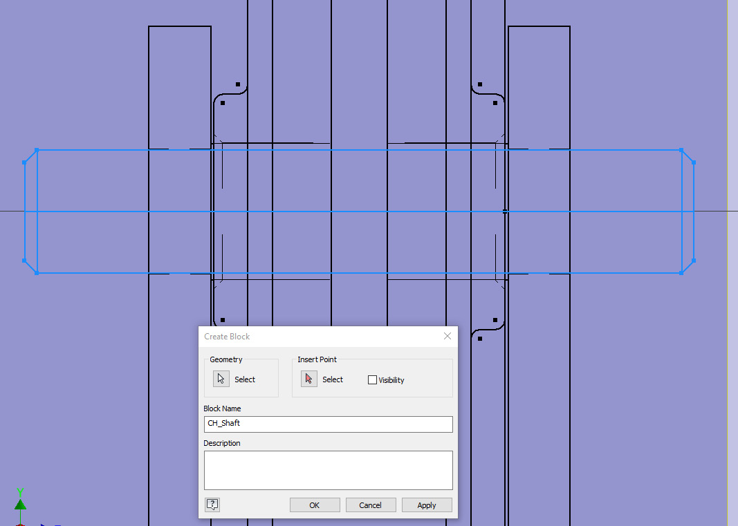
For the final sketch block for the shaft, edit Sketch2 and draw additional lines with the Line command to complete the geometry. This is shown in Figure 2.42. Do not forget to apply a horizontal line across the centerline of the shaft. This is required for a revolve later.
Figure 2.42: Additional two sketch lines created on Sketch2
- Create a third sketch block, as shown in Figure 2.43:
Figure 2.43: Third sketch block to be created from Sketch2
- All sketch blocks required have now been created. These sketch blocks now need to be exported as components. Exit all sketches in the part file and select Make Components from the Manage tab. If you have not saved the file yet, you will be prompted to do so. Save the file in the
Chapter 2 | Crane Hook folder.
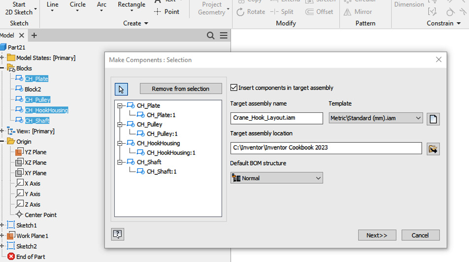
- Expand the Blocks node in the Model Browser and select all created sketch blocks (apart from Block 2) to be created as new components, then select Next.
Figure 2.44: Sketch blocks selected in the Make Components dialog box
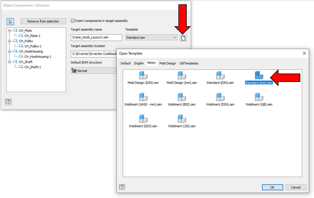
Note that the target assembly name is the same as the name of the original part file, but with the .iam extension. This is the assembly file Inventor will place the newly created components within. Under Template, select the page icon button. Then, navigate to the Metric tab and select Standard (mm) .iam, as shown in Figure 2.45. Then, select OK. Select Next.
Figure 2.45: Template for the assembly
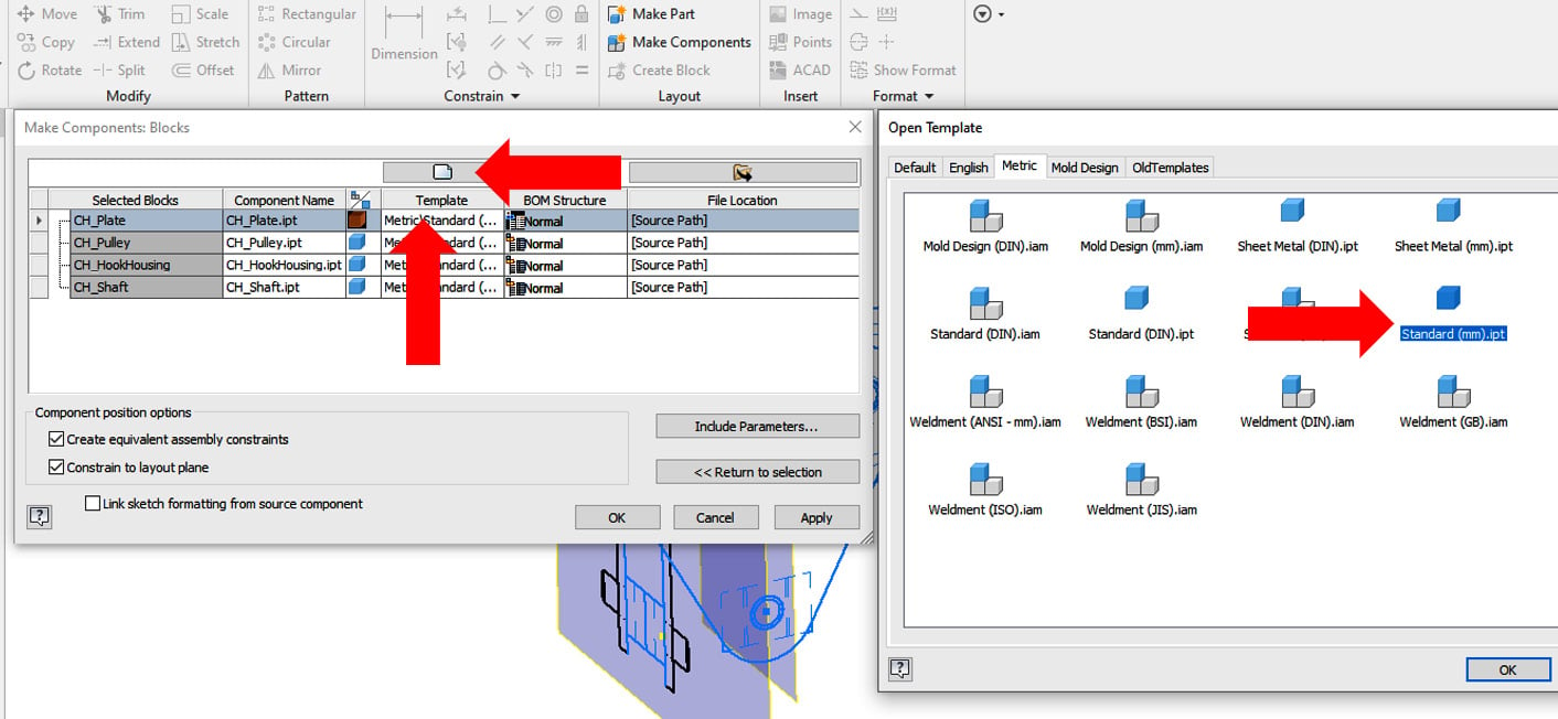
- Select the first sketch block, CH_Plate, from the list. Select the page icon above Template.
- Then, navigate to the Metric tab and select the
Standard (mm) .ipt template for each sketch block, as shown in Figure 2.46:
Figure 2.46: Template for the parts
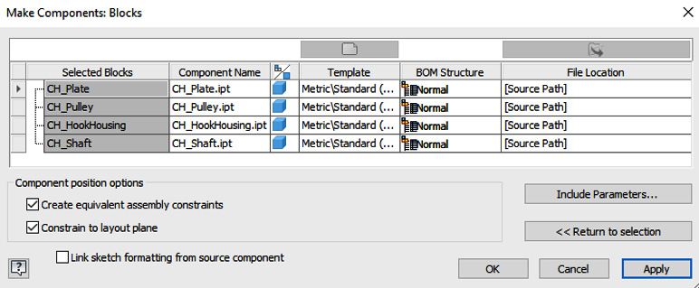
- Repeat steps 27 and 28 for each sketch block in the list, until the list resembles Figure 2.47. Select OK to complete.
Figure 2.47: Sketch blocks in the Make Components menu, with templates configured to Standard (mm) .ipt
Tip – templates
Many of the manual operations in the selecting of templates in these functions can be automatically set once a part file or assembly file template has been created.
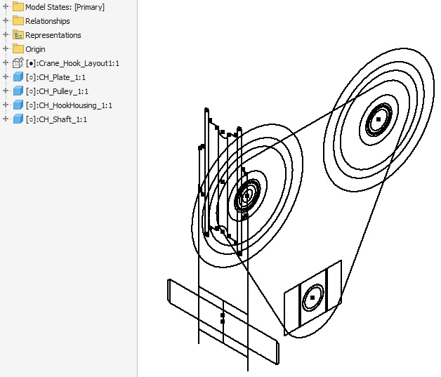
- The newly created components now open in a new assembly
.iam file named Crane_Hook_Layout.iam. Note how in the Model Browser, each sketch block has now been created as a component or part within the assembly. The sketch layout geometry is still present in the Graphics Window, and we can now use this to add 3D geometry to the individual components.
Figure 2.48: Sketch blocks converted into parts in an assembly file
- Move the cursor over the CH_Plate component, right-click, then select Edit.
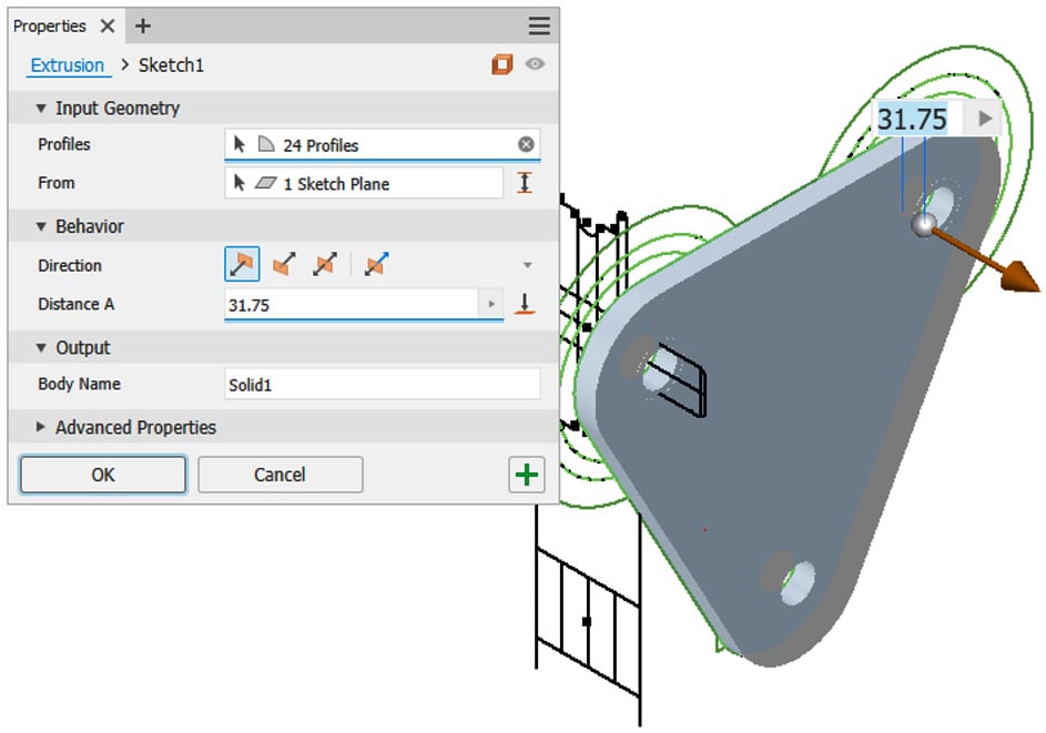
- Select Extrude and pick the profiles of CH_Plate to create the end part. Ensure you do not pick the holes for the shafts. (If you do accidentally fill them in, they can be added later as an Extruded Cut operation.) Leave Direction as the default and set the depth of the extrusion (Distance A) to
31.75 mm. This is shown in Figure 2.49. Then, select OK.
Figure 2.49: Extrusion of CH_Plate using the existing ACAD geometry
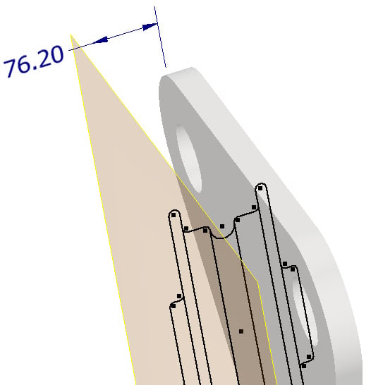
- Select Return from the ribbon to return to the assembly and navigate to the other side of the newly created extrusion feature. Under the Plane command, select Offset from Plane and create a new offset plane from the XY plane at the top level of the assembly, which is a distance of
76.2 mm from it, as shown in Figure 2.50:
Figure 2.50: The placement of an additional work plane
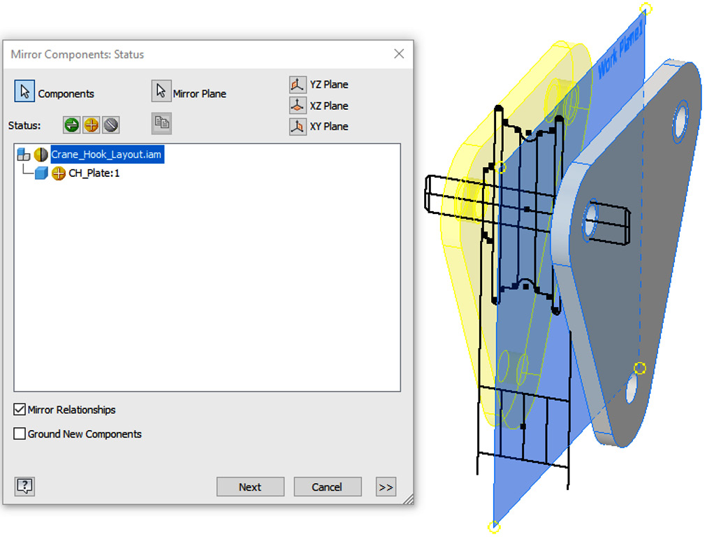
- In the Assemble tab, select Mirror and mirror the newly extruded CH_Plate component using the recently created Offset Work Plane 1 as the mirror plane.
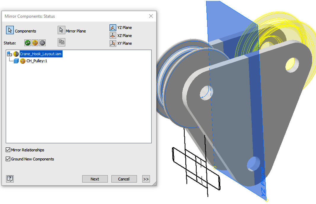
The correct settings to apply in the Mirror Components menu are shown in Figure 2.51. In the Mirror command, select the green icon to activate Reuse Component.
Figure 2.51: Settings applied in the Mirror Component window to apply and the new component in preview
- Select Next and then OK. You have created the first components from the original AutoCAD data that was imported.
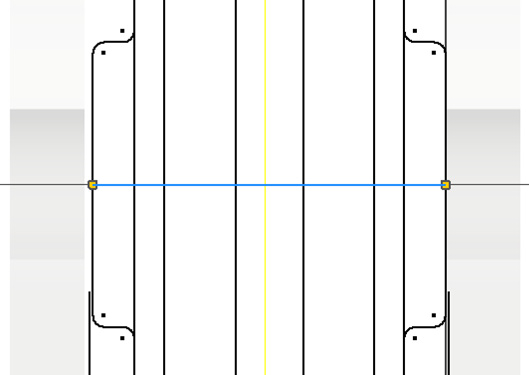
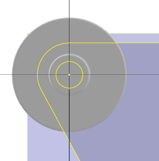
- Next, right-click CH_Pulley from the Model Browser and then select Edit. Then, right-click on Sketch1 in the Model Browser and select Edit Sketch on Sketch1. Draw the additional sketch line, as shown in Figure 2.52. This will act as an axis to revolve the new component.
Figure 2.52: Line applied to the sketch to act as an axis for a revolve operation
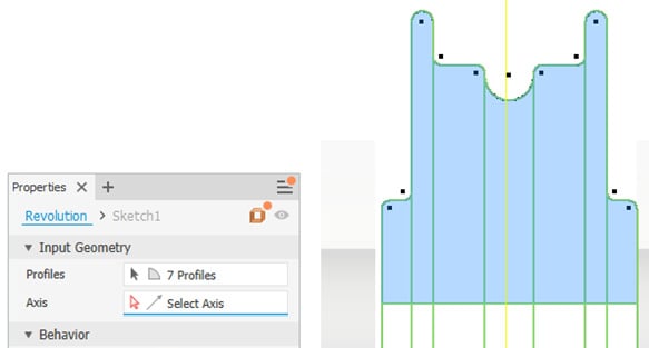
- Select Finish Sketch and then Revolve from the 3D Model tab.
- Select the geometry shown in Figure 2.53 for the profile, and then pick the axis as the newly created sketch line. Then, hit OK.
Figure 2.53: Geometry to select in the revolve operation
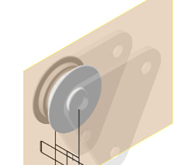
The resulting feature should resemble Figure 2.54:
Figure 2.54: Completed revolve operation shown
- Select Start 2D Sketch and select the face shown in Figure 2.55. Proceed to select Project Geometry and select the geometry shown in Figure 2.55 from
CH_Plate. Select Finish Sketch.
Figure 2.55: Geometry to project
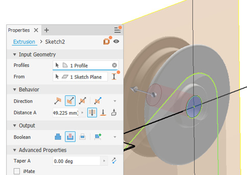
- Select Extrude to create a hole from the circle in Figure 2.55. Figure 2.56 shows the extruded cut and the settings to apply. Select OK to complete.
Figure 2.56: Extruded cut deployed on the newly created feature, using projected geometry from CH_Plate
- Hit Return in the ribbon to return to the top level of the assembly after completion.
- The CH_Pulley component must now be mirrored using the same methodology as CH_Plate. To start, navigate to the top level of the assembly and mark the YZ plane as Visible.
- Select Mirror from the Assemble tab and select CH_Pulley as the component and the YZ plane as the mirror plane. Select Reuse for the Status option, as shown in Figure 2.7:
Figure 2.57: Mirror Components menu with a preview of the new CH_Pulley instance
- Complete the operation by clicking Next, then OK.
- For the crane housing component, the imported geometry is not in the correct place, but we can still utilize it. Edit CH_HookHousing and in the Model Browser, expand the Origin folder under CH_HookHousing. Select Start 2D Sketch on the XY plane of CH_HookHousing.
- Select Project Geometry and project the lines shown in Figure 2.58. If you cannot project the lines, you can also draw a rectangle over the top; it should snap to the end points, so you know the geometry is correct. The result should be a sketch that is a rectangle.
Figure 2.58: Projected lines
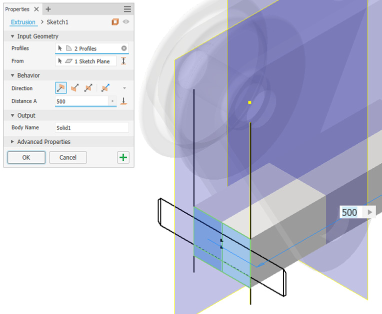
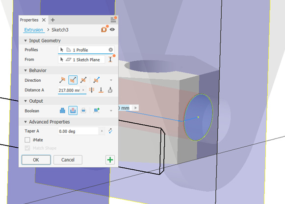
- Select Finish Sketch and then click Extrude. Pick the profiles shown in Figure 2.59 and extrude a distance of
500 mm; this will become CH_HookHousing.
Figure 2.59: 500 mm extrusion to perform
- Select OK to complete.
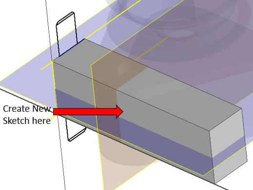
- Now, select Start 2D Sketch on the underside of the newly created extrusion.
Figure 2.60: Location to start a 2D sketch
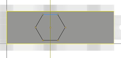
Select Project Geometry and select the face of the extrusion and the YZ work plane of the assembly file. Select the Rectangle command dropdown and select sketch Polygon. Create a six-sided polygon at the intersection, shown in Figure 2.61. Then, apply a horizontal constraint to the top line of the polygon to straighten it.
Figure 2.61: Projected sketch lines and polygon
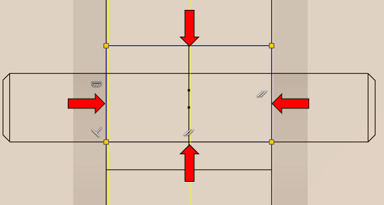
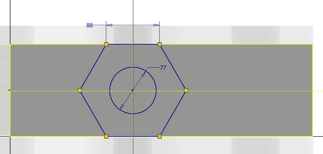
- To constrain the polygon to the correct size, add the following dimensions to the sketched polygon shown in Figure 2.62. Then, sketch a circle from the center point of the polygon with a diameter of
77 mm.
Figure 2.62: Dimensions required and additional sketched circle
- Select Finish Sketch.
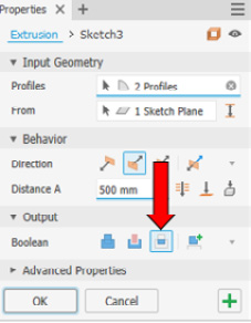
- Select Extrude. Then, select Intersect for the Boolean option.
Figure 2.63: Intersect selected in Extrude
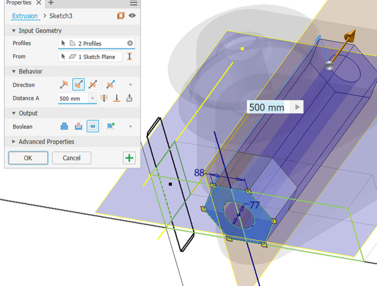
Select the two profiles of the polygon, as shown in Figure 2.64, with the Through All option selected. This will maintain the polygon shape and remove all excess material.
Figure 2.64: Extrude menu shown with profiles selected for the intersect operation
- Complete the operation with OK.
- Select Start 2D Sketch, on the face shown in Figure 2.65, then select Project Geometry of CH_Plates Hole and select Extrude as a Cut, selecting Through All. CH_HookHousing is now complete.
Figure 2.65: Extruded cut menu shown with profiles selected
- Return to the top level of the assembly. The final stage is to create the CH_Shaft component from the original 2D layout.
- Navigate to the the Model Browser, right-click Crane_Hook_Layout1, and select Visibility to turn the original layout on.
- Move the cursor over the CH_Shaft component in the Model Browser and select Edit.
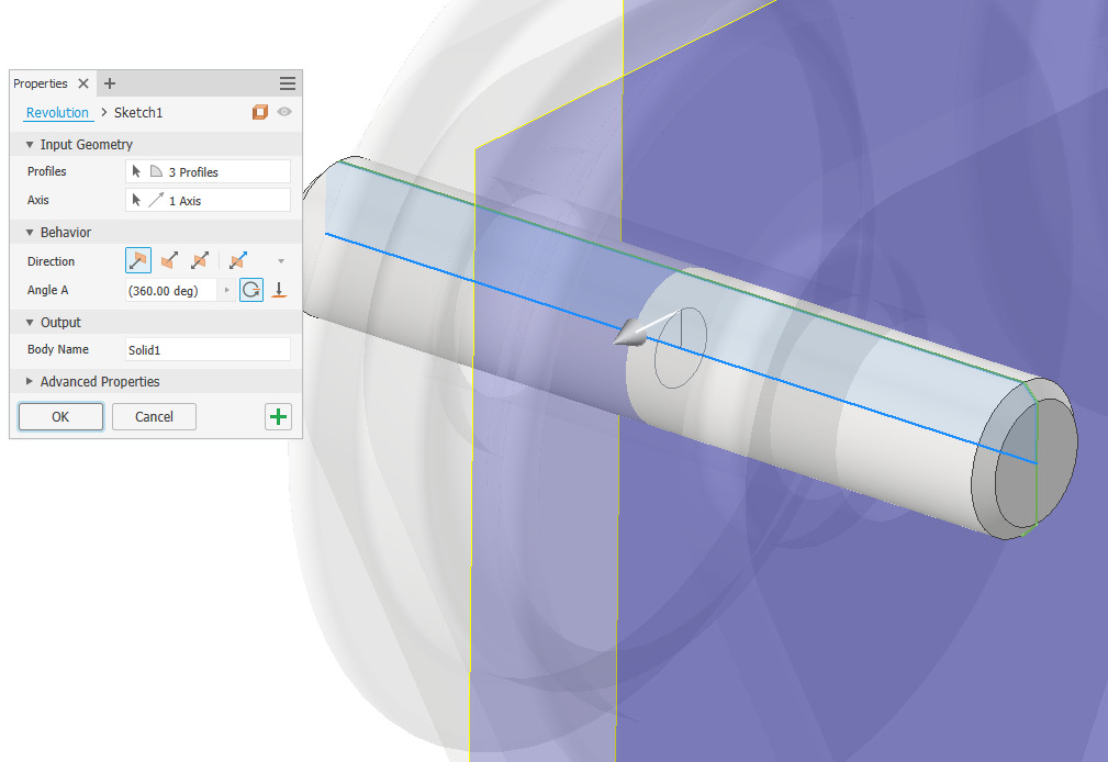
- Select Revolve, then select the profile shown in Figure 2.66. For the axis, select the centerline of the sketch. The preview should resemble Figure 2.66. Select OK to complete the revolve operation.
Figure 2.66: Revolve to complete the CH_Shaft component
- Select Return to go back to the top-level assembly.
- All components have now been created from the initial layout design. The only remaining task is to mirror or copy CH_Shaft to the other two locations.
- Optional: Select the Copy command and assembly constraints to create the final instance of CH_Shaft. The final assembly should resemble Figure 2.67.
Figure 2.67: Completed assembly of the crane hook with three instances of CH_Shaft applied
You have successfully imported and used an existing 2D AutoCAD sketch to create 3D geometry in Inventor as part of a layout design workflow.


 Free Chapter