Sign In Start Free Trial
Account

Add to playlist

Create a Playlist

Modal Close icon
You need to login to use this feature.
  • Book Overview & Buying Squeaky Clean Topology in Blender
  • Table Of Contents Toc
  • Feedback & Rating feedback
Squeaky Clean Topology in Blender

Squeaky Clean Topology in Blender

By : Michael Steppig
4.2 (5)
close
close
Squeaky Clean Topology in Blender

Squeaky Clean Topology in Blender

4.2 (5)
By: Michael Steppig

Overview of this book

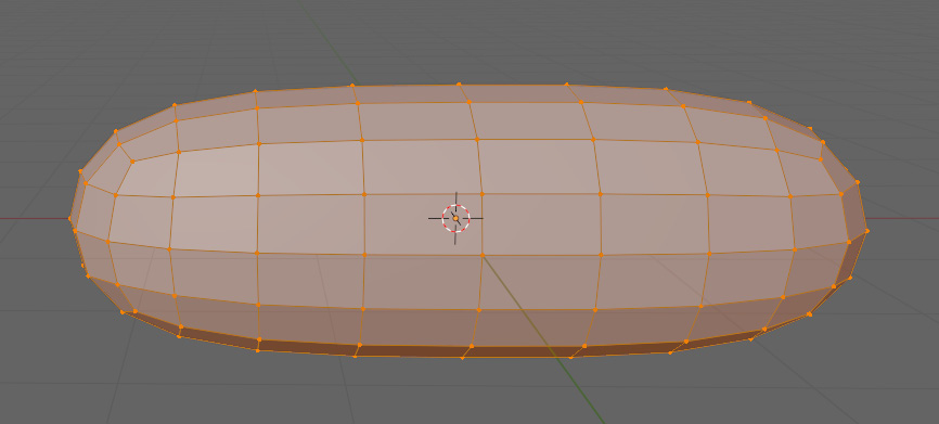
This book is an introduction to modeling and an in-depth look at topology in Blender, written by a Blender topology specialist with years of experience with the software. As you progress through its chapters, you’ll conquer the basics of quad-based topology using triangles and Ngons, and learn best practices and things to avoid while modeling and retopologizing. The pages are full of illustrations and examples with in-depth explanations that showcase each step in an easy-to-follow format. 
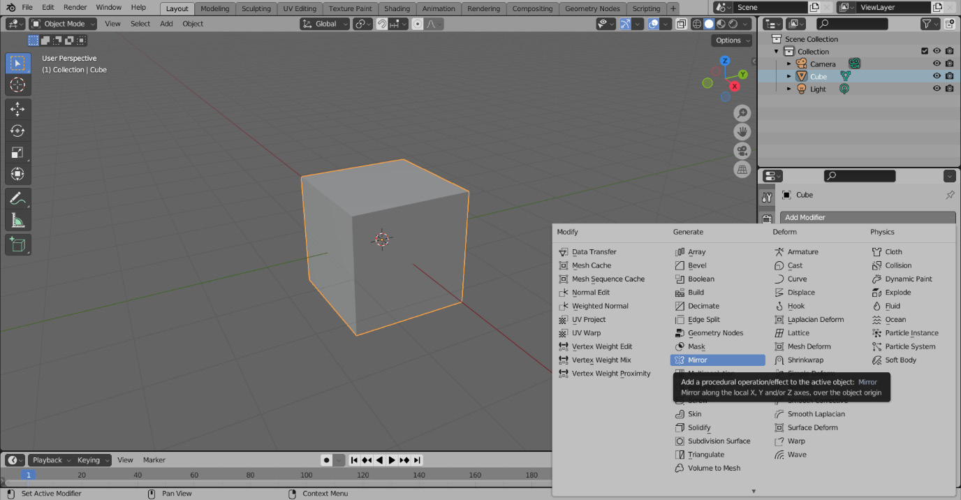
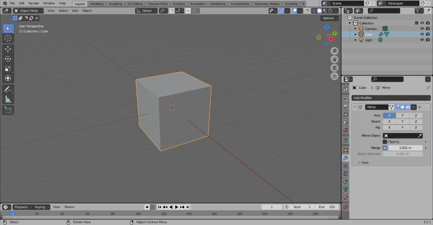
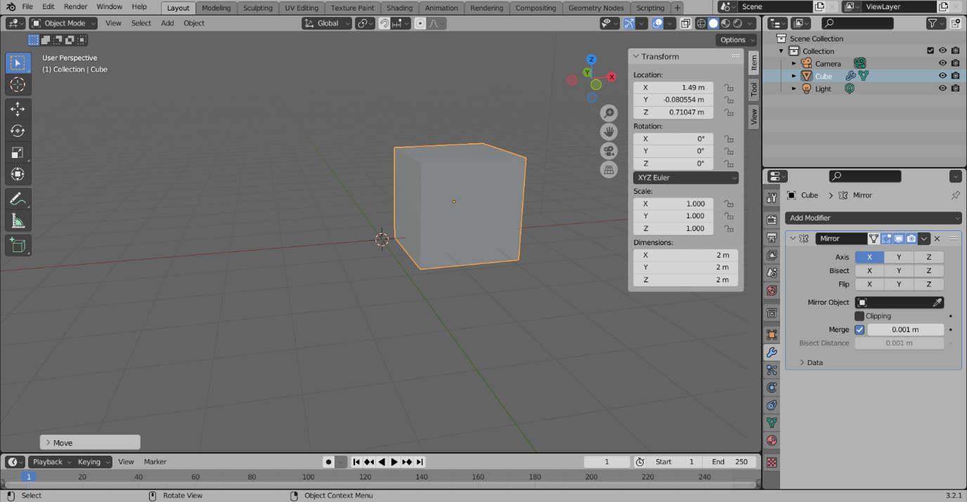
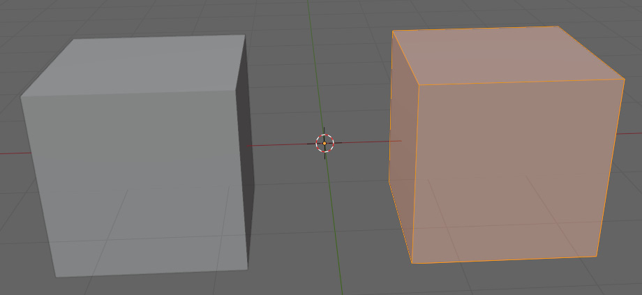
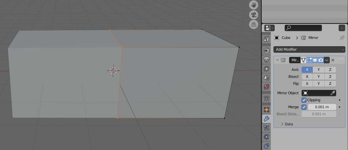
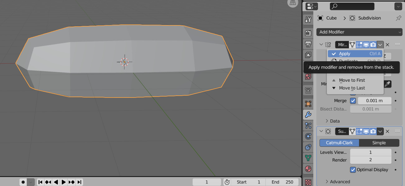
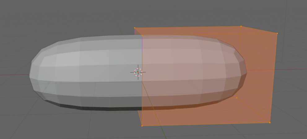
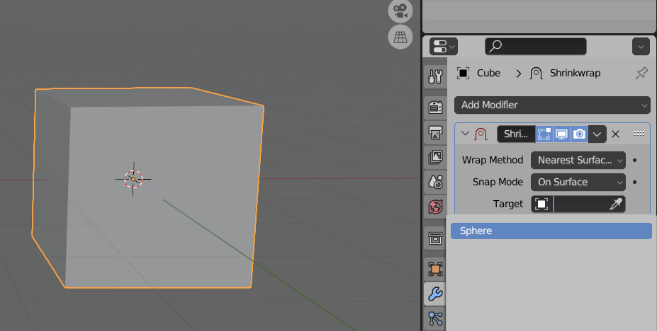
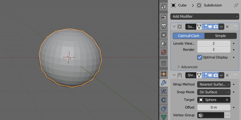
Squeaky Clean Topology in Blender starts by introducing you to the user interface and navigation. It then goes through an overview of the modeling techniques and hotkeys that will be necessary to understand the examples. With the modeling basics out of the way, the next stop on our journey is topology. Working through projects like a character and a sci-fi blaster, the book will illustrate and work through complex topology problems, and present solutions to those problems. These examples focus on deforming character models, non-deforming hard surface models, and optimizing these models by reducing the triangle count. By the end of this book, you will be able to identify the general flow of a shape's topology, identify and solve issues in your topology, and come out with a model ready for UV unwrapping, materials, and rigging.
Table of Contents (13 chapters)
close
close
1
Part 1 – Getting Started with Modeling and Topology
6
Part 2 – Using Topology to Create Appropriate Models

Manipulating a mesh using modifiers

Modeling operations are generally broken up into two general categories, destructive, and non-destructive. Their names are a bit misleading because you can both add and remove geometry by doing both types of operations. The difference is how they go about doing it. All of the modeling methods introduced so far have been destructive. Destructive modeling is when you perform an operation that cannot be tweaked or changed after finalizing the transform. The only way to undo a destructive transform is by using Ctrl + Z. Non-destructive transforms can be changed or completely removed without affecting the base mesh. These transforms affect the mesh indirectly, and are usually used outside of Edit Mode.

There are plenty of ways to affect the mesh indirectly by performing an operation on it outside of Edit Mode. One of the most common ways of doing this is through the Modifier Properties tab in the Properties Editor Type area. The Modifier Properties tab is used to manage modifiers. Modifiers are used to perform non-destructive operations on an object. The Modifier Properties tab can be seen in Figure 1.20.

Figure 1.20 – The Modifier Properties tab

Figure 1.20 – The Modifier Properties tab

The Mirror modifier

An example of one of these modifiers is the Mirror modifier. The Mirror modifier mirrors the object it is put on around the X, Y, or Z axis. To use a modifier on an object, follow these steps:

  1. Make sure the object you want to add it to is selected.
  2. In the Modifier Properties tab, press Add Modifier and navigate to the desired modifier – in this case, the Mirror modifier, as shown in Figure 1.21.
Figure 1.21 – The Mirror modifier in the Add Modifier tab

Figure 1.21 – The Mirror modifier in the Add Modifier tab

  1. Finish adding the modifier by selecting it, and your modifier will appear in the Modifier Properties tab, as displayed in Figure 1.22.
Figure 1.22 – The Mirror modifier

Figure 1.22 – The Mirror modifier

The Mirror modifier works by mirroring the mesh around an object’s origin. The object origin is the little orange dot you see in Object Mode that indicates the object’s orientation compared to the world’s origin. Figure 1.23 shows us a closer look at the origin.

Figure 1.23 – The origin of an object

Figure 1.23 – The origin of an object

  1. Pressing N to open the side panel shows the transforms of the object.
  2. Translating the cube in Object Mode by pressing G and then the LMB to apply the translation will change these variables. This is captured in Figure 1.24.
Figure 1.24 – The translated cube in Object Mode

Figure 1.24 – The translated cube in Object Mode

The Mirror modifier will not be affected by a translation in Object Mode because translation in this mode also moves the origin, and the Mirror modifier mirrors around that.

  1. To see what the Mirror modifier is doing, we have to edit it in Edit Mode because the location of the vertices in this mode are all referenced to the origin of the object. If we translate the cube in Edit Mode, the result is shown in Figure 1.25.
Figure 1.25 – The translating mesh in Edit Mode

Figure 1.25 – The translating mesh in Edit Mode

Now we have a perfectly mirrored cube on either side of our origin. Next, we will look at how to connect the two mirrored halves. To connect the cubes together, follow these steps:

  1. Start by selecting the face facing the origin and deleting just the face. This is to ensure that we do not have any extra faces inside of the mesh.
  2. Next, on the Mirror modifier, make sure Clipping is turned on.
  3. Finally, select the ring of vertices closest to the origin and translate them to the middle, while locking it on the X axis by pressing G and then X. The result should look like Figure 1.26.
Figure 1.26 – Translating in Edit Mode with clipping enabled

Figure 1.26 – Translating in Edit Mode with clipping enabled

The Subdivision Surface modifier

Another common modifier we are going to use is called the Subdivision Surface modifier, or SubD for short. The SubD modifier subdivides the mesh and also performs a smoothing operation on the subdivision. The levels of subdivisions can be adjusted for the viewport and the render can be adjusted separately. Modifiers can also be used destructively. You can apply them by pressing the arrow at the top right of the modifier, pointed out in Figure 1.27.

Figure 1.27 – Applying modifiers in the Modifier tab

Figure 1.27 – Applying modifiers in the Modifier tab

Modifiers affect the mesh from the top of the modifier stack down. So, in this instance, the Mirror modifier is being calculated before the SubD modifier. It is usually best to apply modifiers from the top down to avoid any issues. You must be in Object Mode to apply modifiers. Figure 1.28 shows the mesh in Edit Mode before applying modifiers, and Figure 1.29 shows the mesh after applying them.

Figure 1.28 – The mesh in Edit Mode before applying the modifier

Figure 1.28 – The mesh in Edit Mode before applying the modifier

Figure 1.29 – The mesh in Edit Mode after applying the modifier

Figure 1.29 – The mesh in Edit Mode after applying the modifier

Before applying, the mesh does not change because it is non-destructive. After applying it, it becomes destructive and allows you to modify the mesh directly again. Now that we have an understanding of the Mirror modifier, the next modifier we will use will help us transfer the shape of one mesh to another.

The Shrinkwrap modifier

There are also modifiers that affect the position of the vertices non-destructively. An example would be the Shrinkwrap modifier. The Shrinkwrap modifier projects the vertices from one object onto another object. As an example, we are going to shrink-wrap a cube onto a sphere:

  1. Go into Object Mode and add a cube by pressing Shift + A.
  2. Hover over the mesh.
  3. Select the cube shown in Figure 1.30.
  4. Repeat 1 to 3, only this time, select the UV sphere.
Figure 1.30 – Adding a primitive cube

Figure 1.30 – Adding a primitive cube

After both objects have been added, it should look something like Figure 1.31.

Figure 1.31 – The sphere and cube added on top of each other

Figure 1.31 – The sphere and cube added on top of each other

  1. After this point, we can select the cube and add our Shrinkwrap modifier.
  2. Select the target option on the Shrinkwrap modifier and choose our sphere from the dropdown illustrated in Figure 1.32.
Figure 1.32 – The Object selection tab

Figure 1.32 – The Object selection tab

As soon as this is done, the eight vertices of the cube will be cast onto the surface of the sphere. If we want the cube to conform to the sphere, we will have to give it more geometry to work with. That is where we can use the SubD modifier.

Remember, the modifier stack is calculated from the top down, and we want to add the extra geometry, so we need to put the SubD above the Shrinkwrap modifier.

This can be done by grabbing the top right of the modifier and dragging it above the other modifier. After that, just add another level of subdivision to the viewport, and it should look like Figure 1.33.

Figure 1.33 – The cube shrink-wrapped to the sphere

Figure 1.33 – The cube shrink-wrapped to the sphere

Create a Note

Modal Close icon
You need to login to use this feature.
notes
bookmark search playlist font-size

Change the font size

margin-width

Change margin width

day-mode

Change background colour

Close icon Search
Country selected

Close icon Your notes and bookmarks

Delete Bookmark

Modal Close icon
Are you sure you want to delete it?
Cancel
Yes, Delete

Delete Note

Modal Close icon
Are you sure you want to delete it?
Cancel
Yes, Delete

Edit Note

Modal Close icon
Write a note (max 255 characters)
Cancel
Update Note

Confirmation

Modal Close icon
claim successful

Buy this book with your credits?

Modal Close icon
Are you sure you want to buy this book with one of your credits?
Close
YES, BUY