The setup is the one thing that usually deters many novice enthusiasts from getting started with SBCs. Many times, the instructions are very generic and do not cover all the cases for various types of hardware components. That is why I have dedicated an entire section to the setup of Raspbian on RPi. In this section, we will demonstrate the setup in detail with all the board models ever produced, with the exception of the compute modules.
We need the following components for the setup:
- A Raspberry Pi board of any model.
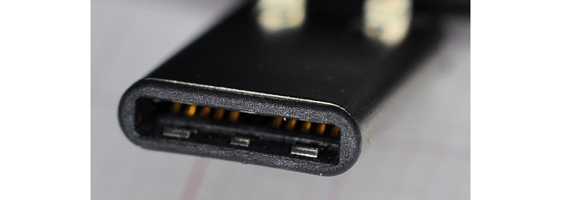
- If you have a Raspberry Pi 4B board, then you will need a power supply of 5V 3A with a USB Type-C pin. Here is a photograph of a USB Type-C pin:
Figure 1.11 – USB Type-C pin
- To be on the safe side, you might want to purchase the official Raspberry Pi 15.3W USB-C power supply by the Raspberry Pi Foundation. The URL for this product is https://www.raspberrypi.org/products/type-c-power-supply/.
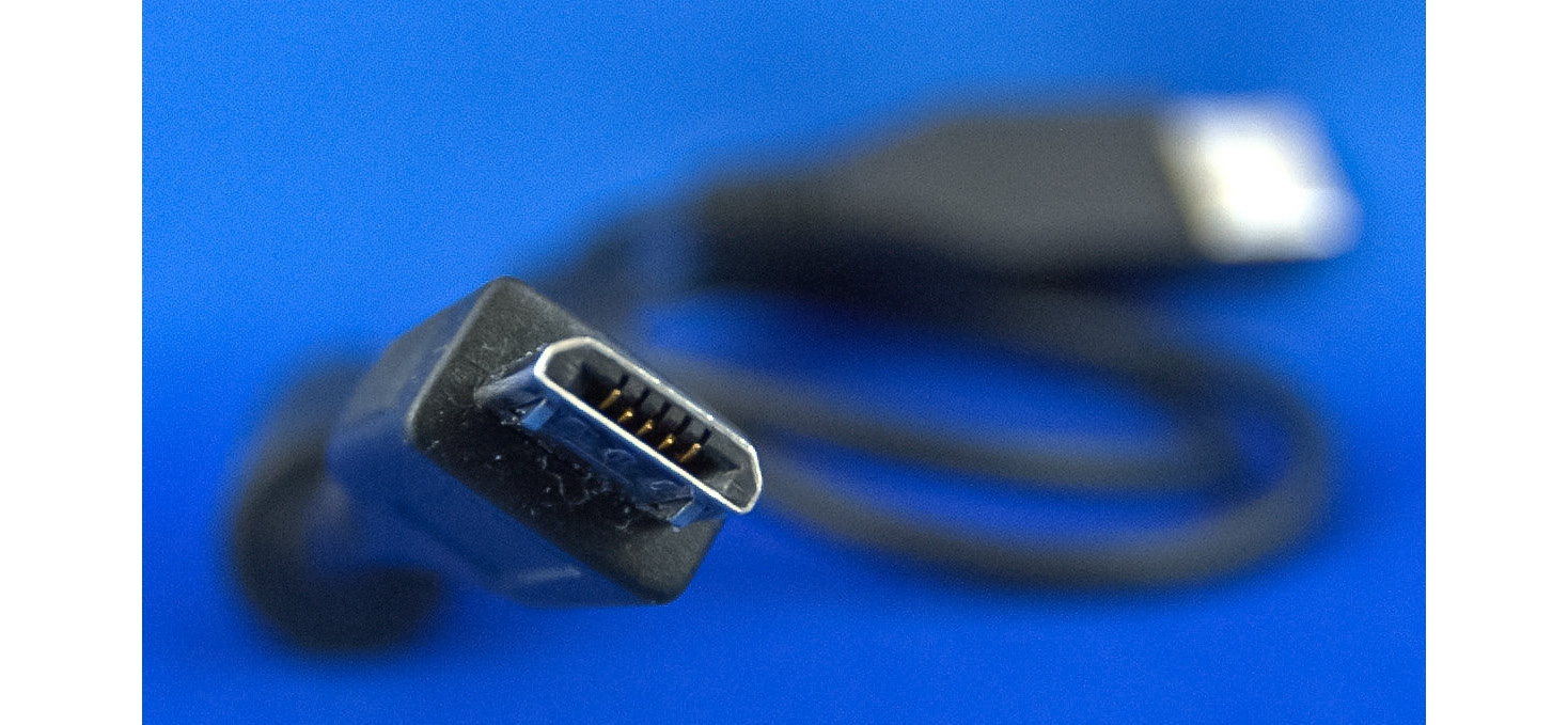
- For all the other models of Raspberry Pi, a 5V 2.5A power supply with a Micro-USB type pin should be compatible. Here's a photograph of a Micro-USB pin:
Figure 1.12 – A Micro-USB pin
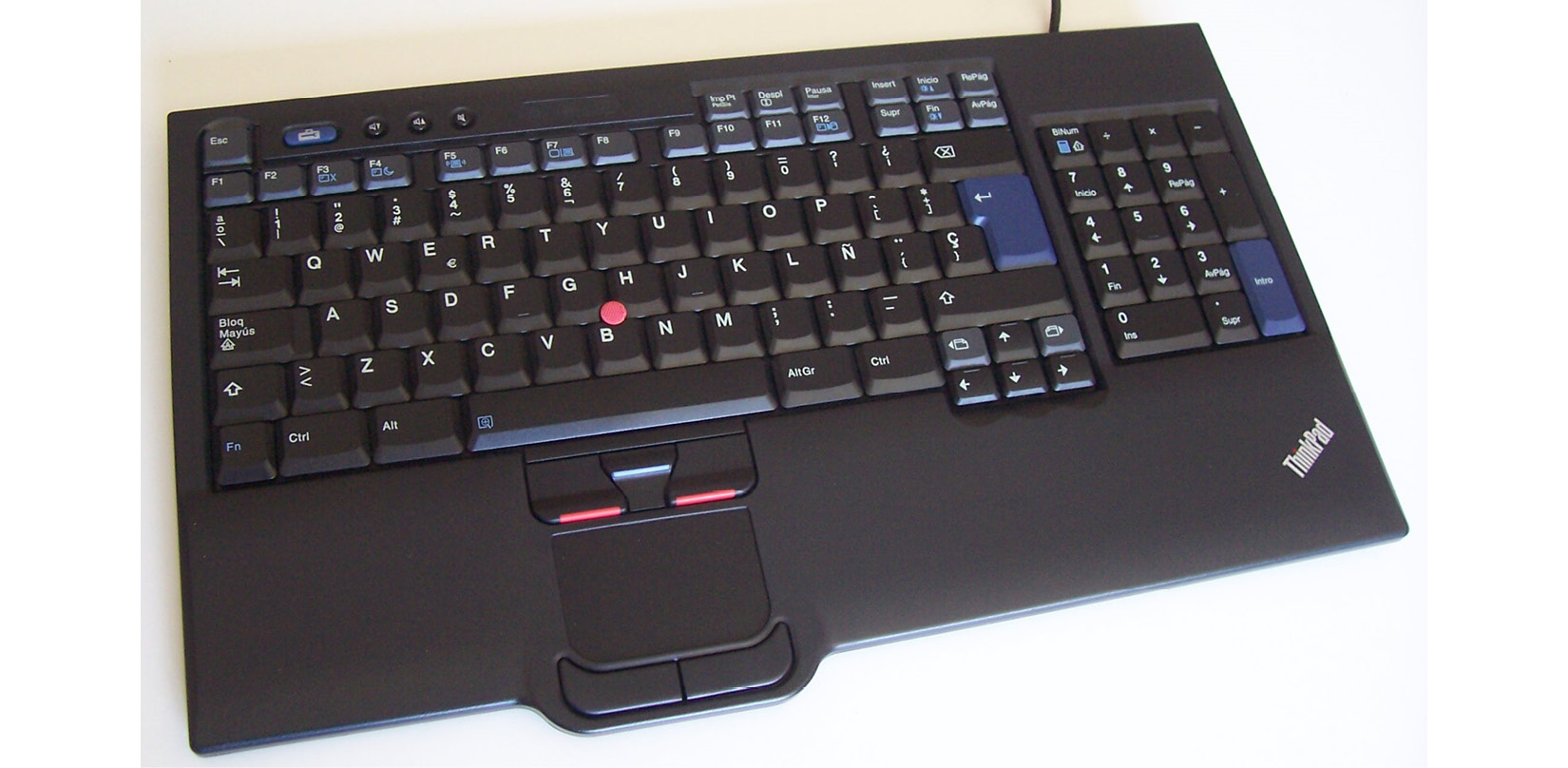
Figure 1.13 – A keyboard with an integrated mousepad
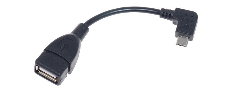
- For RPi Zero and RPi Zero W, the keyboard with a mousepad is mandatory because these board models have only one Micro-USB type of connector to the peripherals interface. Additionally, for RPi Zero and RPi Zero W, we need a USB to Micro-USB OTG converter, as follows:
Figure 1.14 – USB OTG cable
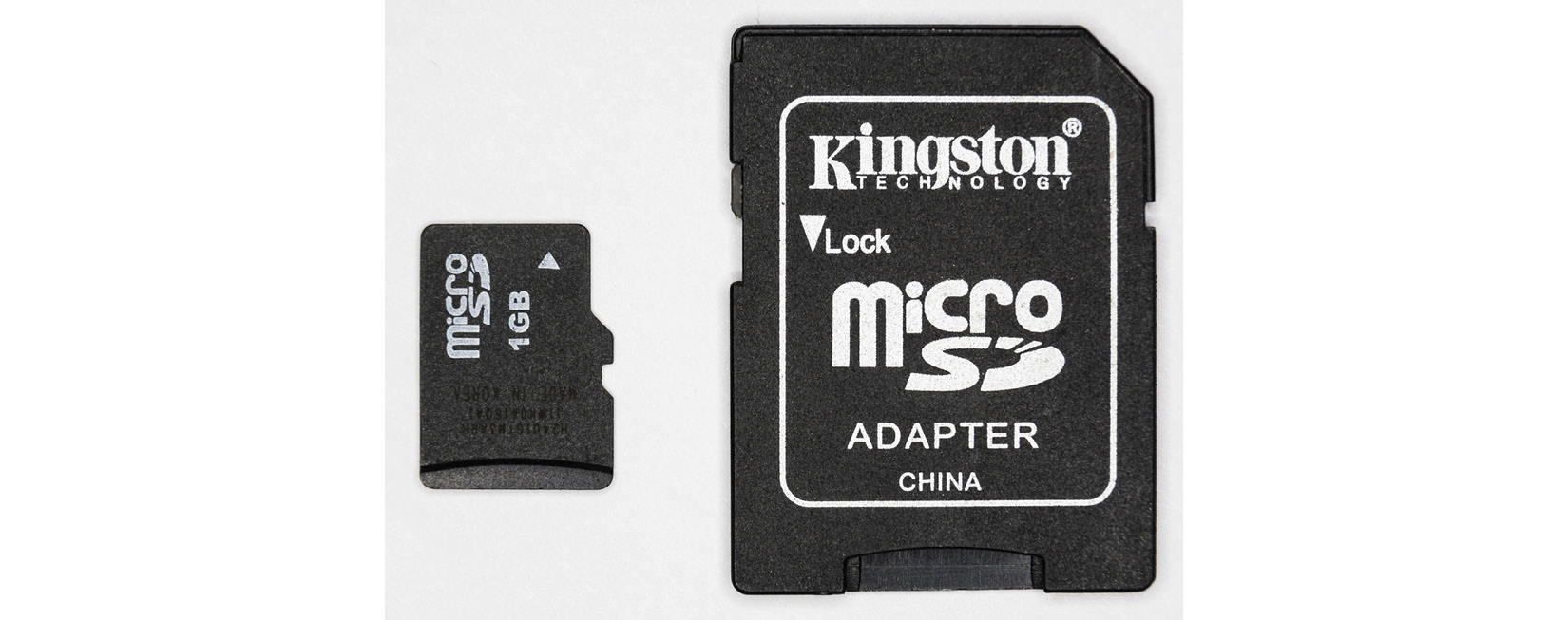
Figure 1.15 – MicroSD to SD card adapter/converter
- An HDMI monitor or a VGA monitor for visual display.
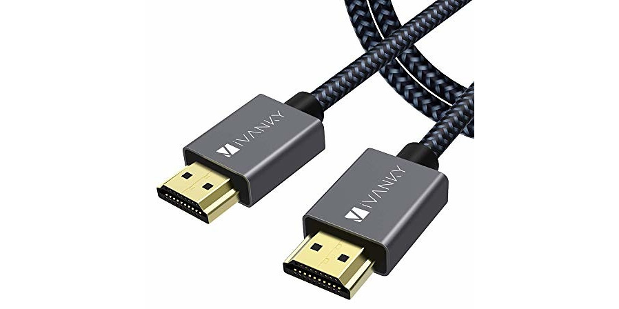
- All RPi board models, except RPi 4B, RPi Zero, and RPi Zero W, have an HDMI output and can be directly connected to the HDMI monitor with an HDMI male-to-male cable:
Figure 1.16 – HDMI cable
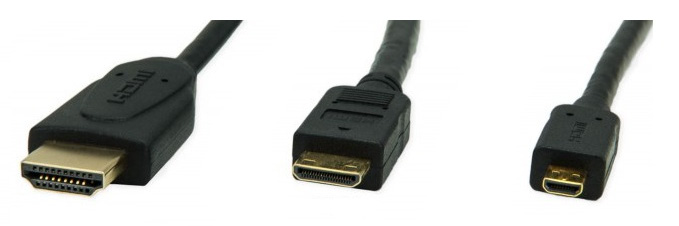
RPi 4B has a micro-HDMI output. Therefore, we need a micro-HDMI to HDMI converter. RPi Zero and RPi Zero W both have mini-HDMI outputs. So, for them, we need a mini-HDMI to HDMI converter. The following photograph shows the HDMI, mini-HDMI, and micro-HDMI ports, respectively:
Figure 1.17 – HDMI, mini-HDMI, and micro-HDMI ports
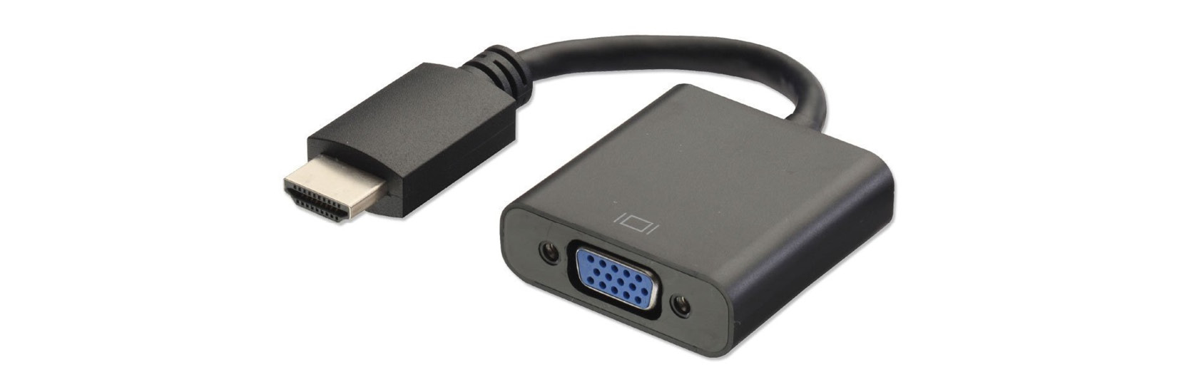
We also need to plug the mini- and micro-HDMI ends to the RPi boards and the HDMI to the monitor. If you are planning to use a VGA monitor, then we will need HDMI/mini-HDMI/micro-HDMI to VGA converters depending on the board models.
Here is a photograph of an HDMI to VGA converter:
Figure 1.18 – HDMI to VGA converter
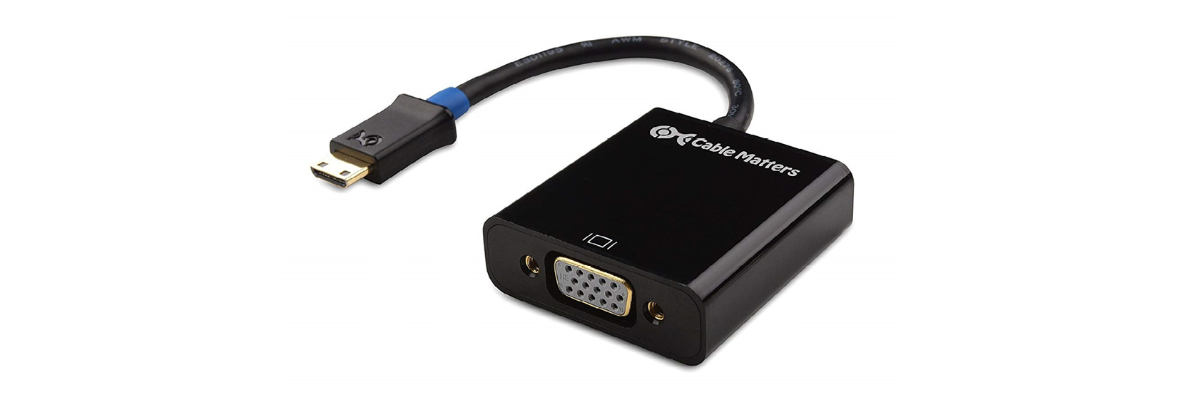
The following is a photograph of a mini-HDMI to VGA converter:
Figure 1.19 – Mini-HDMI to VGA converter
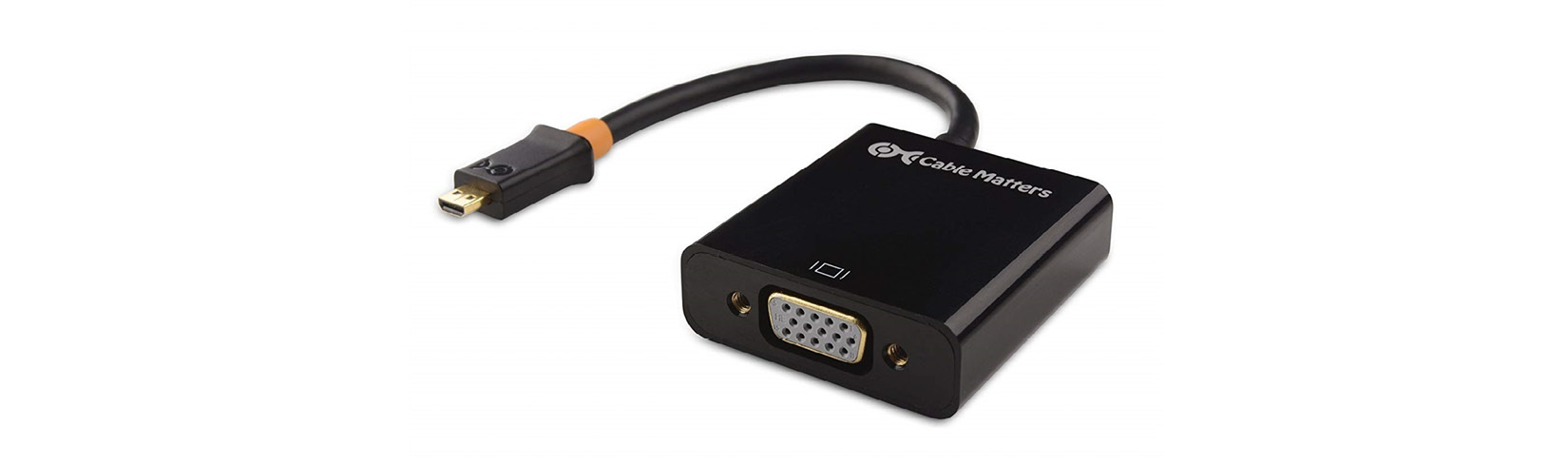
The following is a photograph of a micro-HDMI to VGA converter:
Figure 1.20 – Micro-HDMI to VGA converter
We need a Windows computer and a wired or wireless internet connection.
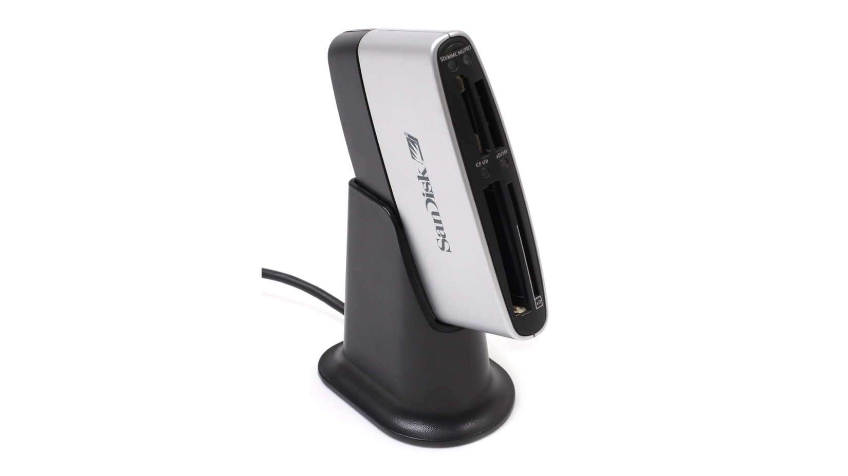
Finally, we require an SD card reader, as follows:
Figure 1.21 – SD card reader
Many laptops have this (SD card reader) feature built-in. So, in that case, a separate reader is not required as we can use the built-in reader.
We will need a few more hardware components by the end of the chapter. We will discuss them when the need arises. For now, we are okay to proceed further.
Downloading the necessary software
To get started, we need to download all of the free software. Follow these instructions to download all the necessary software:
- We need the latest image file of the Raspbian OS. This can be downloaded from the download page of the Raspberry Pi Foundation website at https://www.raspberrypi.org/downloads/raspbian/. The following screenshot shows the various options that are available for download:
Figure 1.22 – Raspbian image download page
- By the time you visit the URL, the page might have been updated, but the download options will usually remain the same. The first option is Raspbian Buster with desktop and recommended software and is the most recommended for beginners. The second option is Raspbian Buster with desktop. The third option is Raspbian Buster Lite and comes with the bare minimum software; it has the smallest size among all the download options.
- We can either download the ZIP file directly, or we can download the torrent file of the image. I recommend downloading the torrent file. Once the torrent file for Raspbian Buster with desktop and recommended software is downloaded, we can download the torrent software from https://www.bittorrent.com/. Download the free classic version and install it on your PC. Then, open the torrent file with BitTorrent and the download will begin. The following is a screenshot of a finished download:
Figure 1.23 – BitTorrent application window
- At the bottom of the screen, we can see the location of the download. Additionally, we can right-click on the finished installation and click on the Open Containing Folder option, as follows:
Figure 1.24 – Opening the location of the downloaded image
This will open the folder that has the ZIP file for the Raspbian OS image.
- We require software for unzipping the file. 7-Zip is the free and open source software for this. We can download the appropriate installable file (32-bit x86 or 64-bit x64) and install it. Once the installation is complete, open the ZIP file using the software. The following is a screenshot of 7-Zip:
Figure 1.25 – 7-Zip application window
Double-click on the ZIP file and then click on the Extract button in the menu. This will extract the file. The extracted file has the img extension.
- We require software to write this image to the microSD card and Win32DiskImager is the perfect software for the task. Download it from http://sourceforge.net/projects/win32diskimager/files/latest/. Run the installation file and install it.
Preparing the microSD card manually
The best way of installing an OS on a microSD card is to do it manually. This allows us to prepare the SD card manually so that we have easier access to the /boot/config.txt configuration file, which must be modified, in a few cases, before booting up the RPi. We will discuss this in detail later. The default Raspbian image has only two partitions—boot and system. I recommend choosing, at a minimum, a 16 GB class 10 microSD card. Then, follow these steps:
- Unpack the fresh microSD card and insert it into the card reader. Plug the card reader into your Windows laptop or computer. Many laptops and computers come with an SD card reader. For these, insert the microSD card into the microSD to SD card adapter, and insert the adapter into the slot for the SD card reader of the computer or laptop.
- Then, a new drive will appear in the left-hand panel of Windows File Explorer. Right-click on the drive and choose Format. Here is a screenshot of the Format window:
Figure 1.26 – Formatting the microSD card
- Make sure that you check the Quick Format checkbox. Then, click on the Start button. It will show a warning message, as follows:
Figure 1.27 – Dialogue box for confirmation
- Click on the OK button to finish formatting.
- Once the formatting is complete, we need to write the Raspbian OS image file to the microSD card. Open
Win32DiskImager and choose the Raspbian OS image file, as shown in the following screenshot:Figure 1.28 – The Win32 Disk Imager application window
- Then, click on the Write button. It will show the following warning box. Simply click on the OK button:
Figure 1.29 – Dialogue box to confirm writing of the image to the microSD card
- Once the OS is successfully written to the SD card, it shows the following message box:
Figure 1.30 – Confirmation message box
This means that the image has been successfully written to the microSD card. Now we can use it to boot up the RPi.
- Now, this step is necessary only if you are using a VGA monitor and not the HDMI monitor. Readers using the HDMI monitor can safely ignore this step. The microSD card's BOOT partition can be accessed using Windows File Explorer. It has the
config.txt file. Double-click and open the file. We must edit the settings in the /boot/config.txt file, as follows, to enable a proper display on the VGA monitor:a) Change #disable_overscan=1 to disable_overscan=1.
b) Change #hdmi_force_hotplug=1 to hdmi_force_hotplug=1.
c) Change #hdmi_group=1 to hdmi_group=2.
d) Change #hdmi_mode=1 to hdmi_mode=16.
e) Change #hdmi_drive=2 to hdmi_drive=2.
f) Change #config_hdmi_boost=4 to config_hdmi_boost=4.
g) Save the file.
The commented lines (that have # at the beginning) are disabled. We must enable these lines by uncommenting them. This can be done by removing # at the beginning of these commented lines.
Note
If you are using Linux or macOS, then you will find the instructions to install the Raspbian OS on your microSD card for these OSes at https://www.raspberrypi.org/documentation/installation/installing-images/.
Booting up the Raspberry Pi for the first time
Let's boot up our Pi for the first time with the microSD card using the following steps:
- Insert the microSD card into the microSD card slot of Pi. RPi 1 Model A and RPi 1 Model B do not have slots for an SD card. So, for these board models, we must use a microSD to SD card converter.
- Connect the Pi to the HDMI monitor. As discussed earlier, in case you have a VGA monitor, connect it using the HDMI/mini-HDMI/micro-HDMI to VGA converter.
- Connect the USB mouse and USB keyboard. It is recommended that you have a single keyboard with a mousepad. For RPi Zero and RPi Zero W, you need to first connect it to a USB OTG cable, and then connect the USB OTG cable to the board.
- Connect the RPi board to an appropriate power supply. Connect the monitor to the power supply. We need to make sure that the power is switched off at this point.
- Ensure you verify all the connections once. Then, turn on the power supply of the monitor. Finally, turn on the power supply for the RPi.
Now, our RPi board will start booting up. The green LED on the board will start blinking. Congratulations! The RPi board is booting for the first time.
Note
If your HDMI monitor is showing no signal, then power down the RPi and change #hdmi_force_hotplug=1 to hdmi_force_hotplug=1 in /boot/config.txt on the microSD card. Boot up the RPi with this changed setting and the HDMI monitor will show the signal.
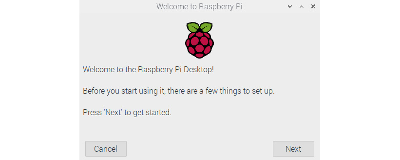
Once the RPi boots up, the Raspbian desktop and a guided setup window appear, as follows:
Figure 1.31 – Welcome window on Raspbian
Click on the Next button, and the following window will appear:
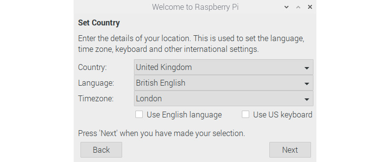
Figure 1.32 – Window for setting the country
In the preceding window, set Country: and Language:. It will automatically select the time zone according to the country you selected. You can change that too if you wish. Click on the Next button, and the following window will appear:
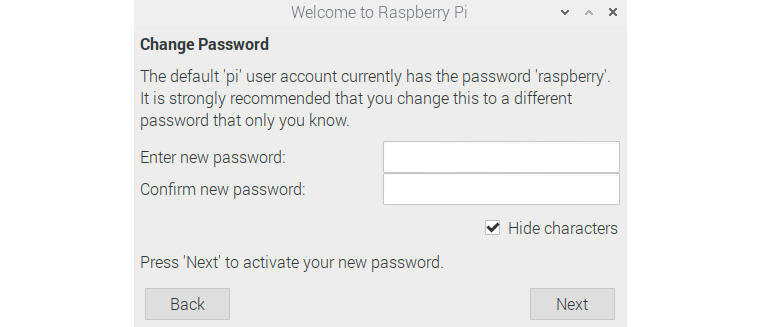
Figure 1.33 – Window for setting a new password
You can choose to set a new password for the default pi user. If you leave it blank, then it will retain the default password. The following is the next window that appears:
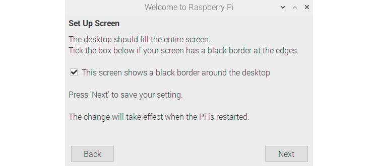
Figure 1.34 – Window for setting up the screen
Check the checkbox if there are black borders on the edges of the desktop view. The Raspbian OS will rectify it upon the next boot. The following window will appear after you click on the Next button, but only if the board model has Wi-Fi:
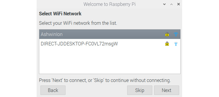
Figure 1.35 – Wi-Fi connections
Choose the network that you know the credentials for, and click on the Next button. The following window will appear:
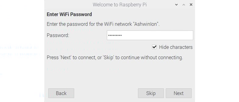
Figure 1.36 – Connecting to the Wi-Fi at my home
Key in your Wi-Fi password here, and click on the Next button. The following window will appear:
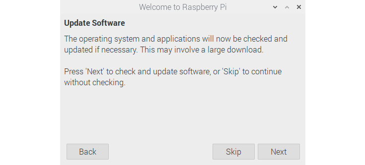
Figure 1.37 – Update Software
We can update the Raspbian OS and installed software here. We are going to learn how to do it manually in the latter part of this chapter. Click on the Skip or Next button, and the following window will appear:
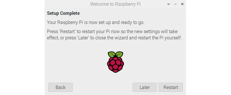
Figure 1.38 – Confirmation of completing the initial setup
We have finished most of the setup. Now, there are a few more things to do before we reboot out RPi, so click on the Later button.
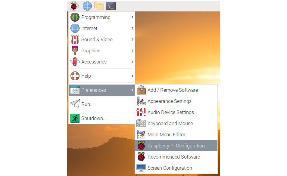
Now, in the top-left corner of the desktop, you should see a Raspberry icon. It is the menu for Raspbian and functions in a similar way to the Windows logo on Microsoft Windows. Click on the logo and navigate to Preferences | Raspberry Pi Configuration:
Figure 1.39 – Raspberry Pi Configuration in the Raspbian menu
This is the Raspberry Pi Configuration tool. It will open a window as follows, and we can change the settings of the Raspberry Pi board:
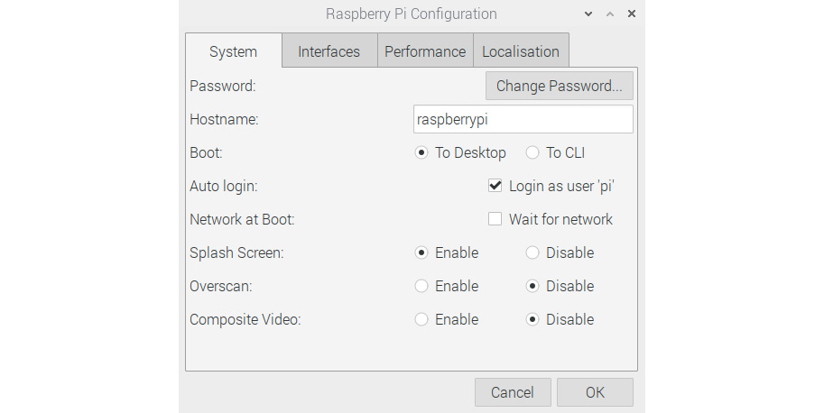
Figure 1.40 – Configuring the system
The preceding screenshot is the System tab. As of now, there is no need to change anything here. The following is the Interfaces tab:
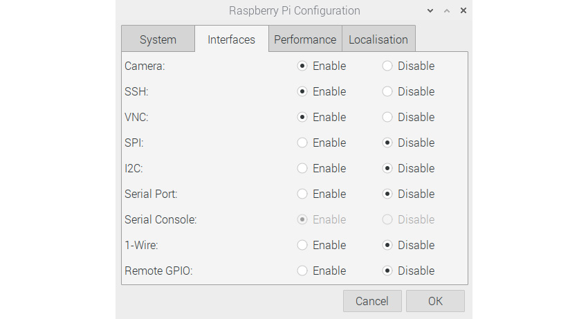
Figure 1.41 – Configuring interfaces
Enable the camera, SSH, and VNC. The following is the Performance tab:
Figure 1.42 – Memory and Overclock options
This menu has an option for overclocking and GPU memory. For the RPi 4B, overclocking is disabled. We will learn how to overclock an RPi 4B board manually in the next chapter. The Localisation tab is as follows:
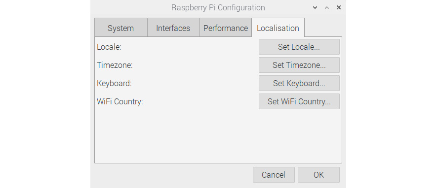
Figure 1.43 – Localisation options
You might want to change these settings as per your region of residence.
Once all these settings have been changed as per our choice, we can restart the RPi board by clicking on the Shutdown button in the Raspbian menu:
Figure 1.44 – Rebooting the Pi
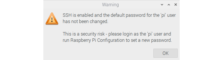
Here, we find the option to reboot the RPi. Once we reboot, and if we have chosen to retain the original password for the default user, pi, the following warning message window will appear when booting up:
Figure 1.45 – Message after rebooting if the default password has not been changed
And this will keep on appearing after every boot as long as we choose to retain the default password.
Connecting various RPi board models to the internet
We can directly plug in the Ethernet cable to the RJ45 Ethernet port Pi boards. This will automatically detect the connection and connect to the internet.
Note
Make sure that DHCP (Dynamic Host Configuration Protocol) is enabled at the Wi-Fi router, the managed switch, or the internet gateway.
PRi 1 A, PRi 1 A+, RPi Zero, RPi Zero W, and RPi 3 A+ do not have Ethernet ports. However, RPi Zero W and RPi 3 A+ have built-in Wi-Fi. We can use a USB Wi-Fi dongle for the remaining models:
Figure 1.46 – USB Wi-Fi adapter
Plug this Wi-Fi adapter into the USB port. If the USB ports are not enough, then use a powered USB hub. For Raspberry Pi Zero, we need to use an additional USB OTG cable, as discussed earlier.
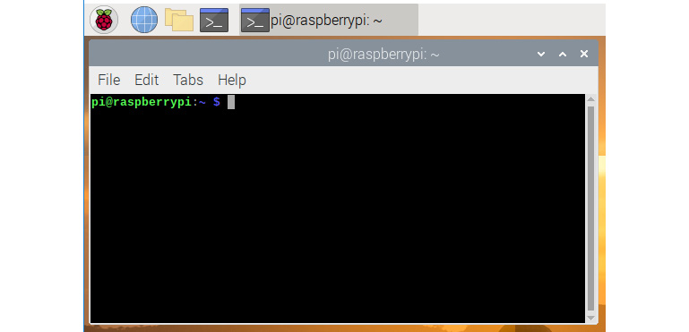
After plugging in the USB Wi-Fi adapter, we need to open lxterminal. This is the command-line utility. We can find it as a small black icon in Raspbian's taskbar and under Accessories in the Raspbian menu. Once we click on it, the following window will appear:
Figure 1.47 – Raspberry Pi LXterminal window
We can type in the Linux commands here. After typing them in, press Enter to execute the command. We have opened this so that we can manually configure the network interface of Raspbian. It is quite easy. All the network-related information is stored in the /etc/network/interfaces file. To connect to the Wi-Fi after plugging in the USB Wi-Fi dongle, we need to add a few entries to this file. First, take the backup of the original file by executing the following command:
mv /etc/network/interfaces /etc/network/interfaces.bkp
Then, we can create the interfaces file from scratch by running the following command:
sudo nano /etc/network/interfaces
The preceding command will open the network interface's file with a plain text editor known as nano. It is a simple WYSIWYG editor. Enter the following lines there:
source-directory /etc/network/interfaces.d
auto lo
iface lo inet loopback
auto wlan0
allow-hotplug wlan0
iface wlan0 inet dhcp
wpa-ssid "AshwinIon"
wpa-psk "internet1"
After entering the lines, press Ctrl + X and then press Y. In the preceding settings, substitute AshwinIon with your own SSID and internet1 with a password for the same. Then, run the following command in Command Prompt:
sudo service networking restart
This restarts the networking service and connects to the Wi-Fi. In any case (Ethernet or Wi-Fi), the RPi is assigned with a unique IP address. We can find it out by running the ifconfig command at lxterminal. The output of the command will have the Ipv4 address listed under inet.
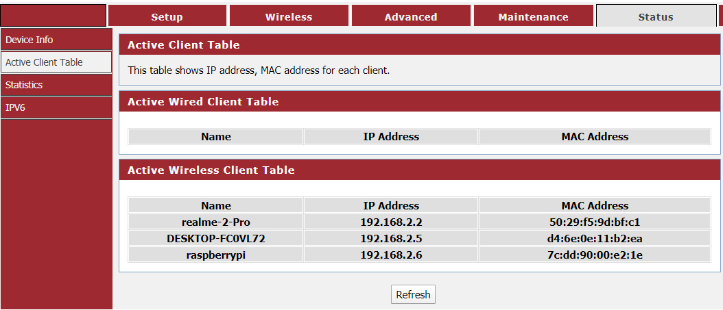
Another way to know the IP address of the RPi is to check the active client tables in the router or the managed switch that the RPi board is connected to. The following is a screenshot of my router's active client table where we can see an entry for RPi:
Figure 1.48 – Active client table of a home Wi-Fi router


 Free Chapter