-
Book Overview & Buying
-
Table Of Contents

-
Feedback & Rating

M5Stack Electronic Blueprints
By :
M5Stack Electronic Blueprints
By:
Overview of this book
As an embedded systems developer or an IoT developer, you can often face challenges in maintaining focus on prototyping a product concept while using a specific high-level programming language for implementation. To overcome these challenges, the M5Stack Core platform uses an ESP32 microcontroller and block code that allows you to focus on product creation and application instead of the high-level programming language. M5Stack Electronics Blueprints presents various design and prototyping approaches as well as UI layout and electronics interfacing techniques that will help you to become skilled in developing useful products effectively.
This book takes you through a hands-on journey for a better understanding of the ESP32 microcontroller and the M5Stack Core's architecture. You’ll delve into M5Stack Core topics such as electronic units, light, sound, motion devices, interfacing circuits, SNAP circuit kits, Arduino applications, and building Bluetooth and Wi-Fi IoT devices. Further, you’ll explore various M5Stack core applications using a project-based learning method, including the fascinating 32-bit microcontroller device technology.
By the end of this book, you’ll be able to design and build interactive, portable electronic controllers, IoT, and wearable devices using the M5Stack Core.
Table of Contents (14 chapters)
Preface

Part 1: M5Stack Electronics Hardware Architecture
 Free Chapter
Chapter 1: Exploring the M5Stack Core
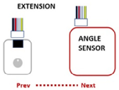
Chapter 2: Hands-On with M5Stack Units
Chapter 3: Lights, Sound, and Motion with M5Stack
Part 2: M5Stack Electronic Interfacing Circuit Projects
Chapter 4: It’s a SNAP! Snap Circuits and the M5Stack Core
Chapter 5: Solderless Breadboarding with the M5Stack
Chapter 6: M5Stack and Arduino
Part 3: M5Stack IoT Projects
Chapter 7: Working with M5Stack and Bluetooth
Chapter 8: Working with the M5Stack and Wi-Fi
Index
Customer Reviews