-
Book Overview & Buying
-
Table Of Contents

-
Feedback & Rating

Hands-on ESP32 with Arduino IDE
By :
Hands-on ESP32 with Arduino IDE
By:
Overview of this book
ESP32 is a versatile microcontroller and a great starting point for anyone venturing into the IoT realm, but its configuration and interfacing of sensors can be challenging for new users. Arduino Integrated Development Environment (IDE) simplifies programming, uploading code, and utilization of ESP32 capabilities, enabling users to incorporate it into their IoT projects with ease. This book will help you learn the essentials of sensing, networking, data processing, and applications with ESP32, laying a strong foundation for further IoT development.
Starting with ESP32 and Arduino Ide 2.0 basics, you'll first explore practical implementation examples of interfacing sensors with ESP32. These examples will also teach you how to interface the ESP32 camera and display modules with ESP32. As you progress, you’ll get to grips with IoT network and data protocols, as well as the many options they unlock within IoT applications. The book will also help you leverage your newly acquired knowledge with exciting projects ranging from smart connected devices to data loggers and automation.
By the end of this book, you'll confidently navigate ESP32 projects with newfound knowledge and skills, know what IoT protocol to select for your applications, and successfully build and deploy your own IoT projects.
Table of Contents (15 chapters)
Preface

Part 1 – Introduction: Getting Familiar with ESP32
 Free Chapter
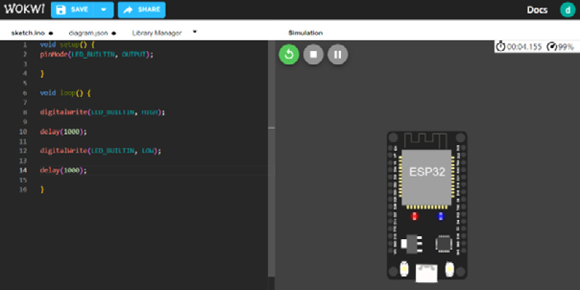
Chapter 1: IoT with ESP32 using Arduino IDE
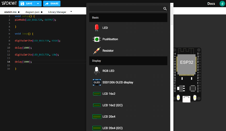
Chapter 2: Connecting Sensors and Actuators with ESP32
Chapter 3: Interfacing Cameras and Displays with ESP32
Part 2 – IoT Protocols and ESP32
Chapter 4: Implementing Network-Based Protocols with ESP32
Chapter 5: Choosing the Right Data-Based Protocols for Your ESP32 Projects
Part 3 – Practical Implementation
Chapter 6: Project 1 – Smart Plant Monitoring System Using ESP32, Messaging Services, and the Twitter API
Chapter 7: Project 2 – Rent Out Your Parking Space
Chapter 8: Project 3 – Logging, Monitoring, and Controlling using ESP32
Chapter 9: From Arduino IDE to Advanced IoT Development – Taking the Next Steps
Index
Customer Reviews